Welding fixture

A technology for welding fixtures and bottom plates, applied in welding equipment, auxiliary welding equipment, welding/cutting auxiliary equipment, etc., can solve the problems of large position accuracy error, difficulty in improving product grades, large workpiece error, etc., and achieve stable positioning reference Effect

Inactive Publication Date: 2011-08-17
昇辉智能科技股份有限公司
View PDF8 Cites 1 Cited by
  • Summary
  • Abstract
  • Description
  • Claims
  • Application Information

AI Technical Summary

Problems solved by technology

[0002] In the existing welding process, there is no reliable positioning equipment to assist welding. We can only measure and position first, and then weld. position, so that the welded workpiece has large errors, low efficiency, and greater positional accuracy errors, making it difficult to improve product grades

Method used


Image

  • Welding fixture
  • Welding fixture
  • Welding fixture

Examples


Embodiment 1

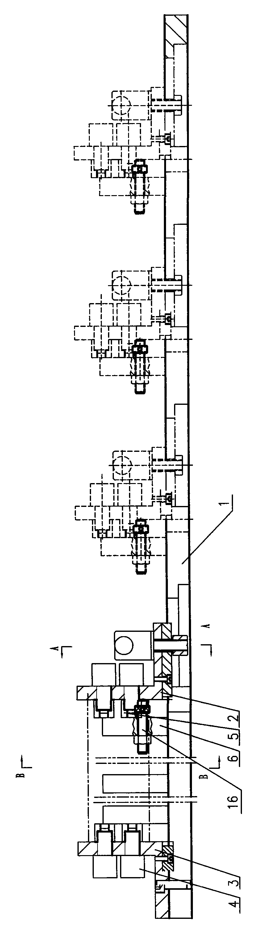
[0012] Embodiment 1, a kind of welding fixture, with reference to figure 1 , figure 2 , image 3 One end of the bottom plate 1 is fixed with a fixed curved plate 3, and the bottom plate 1 is provided with a movable curved plate 2 that can be moved and positioned along the bottom plate 1. The facades of the fixed curved plate 3 and the movable curved plate 2 are opposite, and the fixed curved plate 3 and the positioning screw sleeve 5 connected to the workpiece by the movable positioning pin 4 on the facade of the mobile bending plate 2, the thread at the end of the movable positioning pin 4 is connected with the internal thread of the positioning screw sleeve 5, and the positioning pin 4 can be positioned by rotating the movable positioning pin 4. The screw sleeve 5 is fixed on the elevation of the movable curved plate 2 and the fixed curved plate 3, and V-shaped blocks 6 are arranged at intervals on the bottom plate 1, and positioning screws 16 are housed on the V-shaped bl...

Embodiment 2

[0013] Embodiment 2, a kind of welding fixture, refer to figure 1 , figure 2 , figure 2 , is on the basis of embodiment 1, the inboard of the two arms of V-shaped block 6 is provided with supporting block 7, and supporting block 7 is positioned on the V-shaped block 7 by bolt activity, and other is identical with embodiment 1.

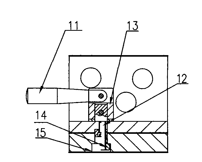
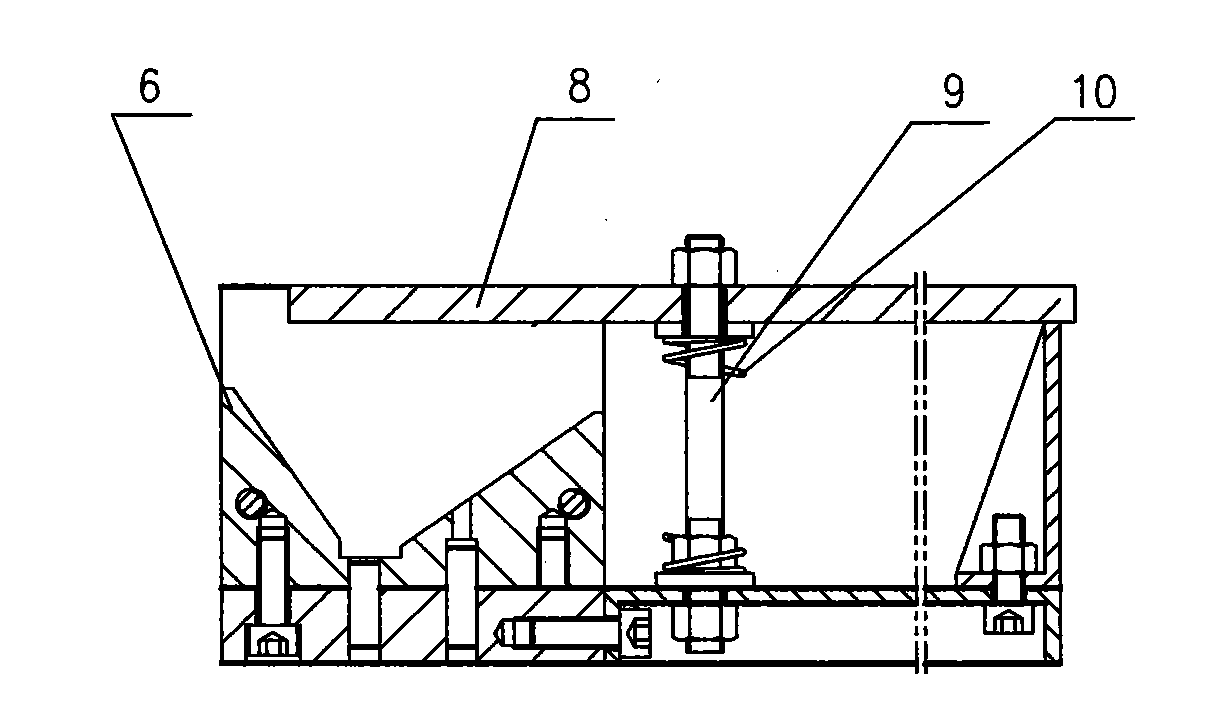
[0014] When using the present invention, the workpiece is first placed on the V-shaped block 6, and then the movable curved plate 2 is pushed to lean against the positioning surface of the positioning screw 16, and the handle 11 is turned to fasten the movable curved plate 2 to realize length positioning, and then the positioning The screw sleeve 5 is installed on the positioning pin 4 and tightened, and then the pressure plate 8 is turned to the clamping position to press the workpiece to be welded; when unloading, just loosen the nut of the pressure plate 8, and the spring 10 will bounce it up, and loosen the positioning pin Unclamp the handle 11...


PUM


Abstract

The invention discloses a welding fixture. The welding fixture is characterized in that a fixed bending plate and a moving bending plate capable of moving location along a bottom plate are fixed on one end of the bottom plate; the vertical surfaces of the fixed bending plate and the moving bending plate face to each other, and are connected with location screw sleeves through a movable location pin; V-shaped blocks provided with locating screws are arranged in the upper surface of the bottom plate at intervals; a T-shaped groove for mounting a T-shaped nut is formed on the bottom plate on the side of the moving bending plate beside the V-shaped block; a handle base is arranged on the horizontal plane of the moving bending plate; the handle base is respectively connected with a handle and a screw through a cylindrical pin; the screw can fixedly fit with the T-shaped nut; a double-thread screw having one end fixed on the bottom plate is arranged close to the V-shaped block; a pressure plate for covering the opening of the V-shaped block is arranged on the other end of the double-thread screw; and a spring is sheathed on the double-thread screw. The welding fixture is reliable in location and convenient in operation and loading workpieces, and has the advantages of simple and novel structure and wide application range.

Description

technical field [0001] The invention belongs to the field of welding processing equipment, and in particular relates to a welding fixture suitable for a complete set of switchgear for power transmission and distribution. Background technique [0002] In the existing welding process, there is no reliable positioning equipment to assist welding. We can only measure and position first, and then weld. Position, so the welded workpiece has large errors, low efficiency, and greater positional accuracy errors, making it difficult to improve product grades. Contents of the invention [0003] The object of the present invention is to improve the deficiencies of the prior art and provide a welding fixture with reliable positioning, convenient clamping of workpieces, simple and novel structure, convenient operation and wide application range. [0004] The present invention is achieved in this way. A welding fixture is composed of a base plate. It is characterized in that a fixed ben...

Claims


Application Information

Patent Timeline
IPC IPC(8): B23K37/04
Inventor 纪法清崔静葛榄刘德业赵锦航张索航
Owner 昇辉智能科技股份有限公司
Why Eureka
Try Eureka