Scanning method, scanning device and scanner

A scanning method and technology of a scanning device, applied in the field of scanners, can solve the problems of lowering scanning quality, lowering scanning resolution scanning lines, etc., and achieve the effects of ensuring scanning quality, shortening scanning time, and shortening output signal time.

Inactive Publication Date: 2011-08-17
QISDA SUZHOU +1
View PDF3 Cites 1 Cited by
  • Summary
  • Abstract
  • Description
  • Claims
  • Application Information

AI Technical Summary

Problems solved by technology

[0004] At present, the methods to shorten the scanning time mainly include reducing the scanning resolution or reducing the number of scanning lines. Although these two methods can shorten the scanning time, they will reduce the scanning quality.

Method used


Image

  • Scanning method, scanning device and scanner
  • Scanning method, scanning device and scanner
  • Scanning method, scanning device and scanner

Examples


Embodiment Construction

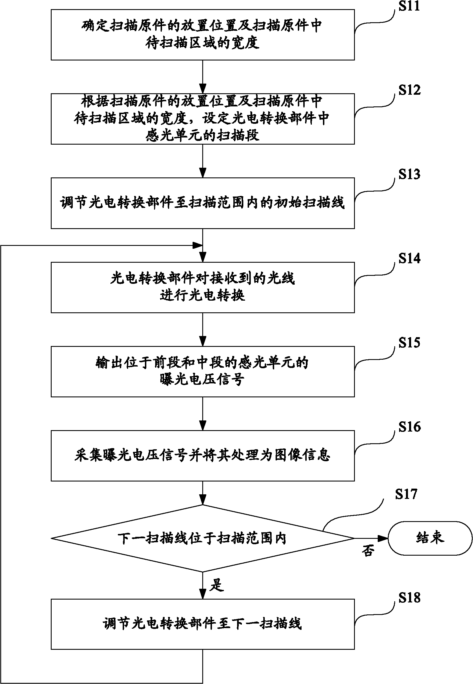
[0037] The width of the photoelectric conversion part in the scanner is much larger than that of the scanned original, and often only a part of the scanned original needs to be scanned. For example, assuming that the photoelectric conversion component has 10,000 photosensitive units in the X direction, relative to an A4-sized scanned original, the width of the entire scanned original corresponds to only 7,200 photosensitive units, and usually the scanned original is provided with page margins The character or picture to be scanned is only a part of the entire scanned original.

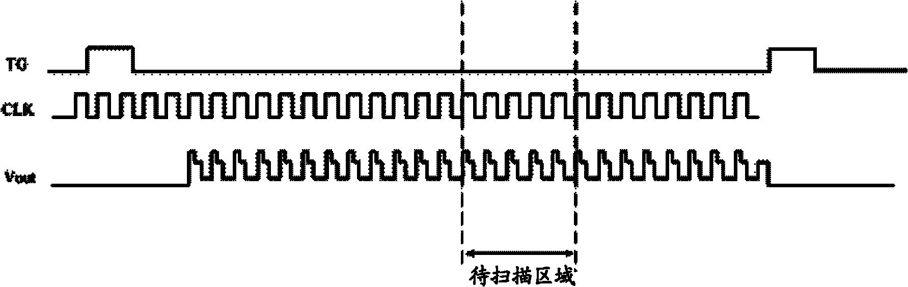
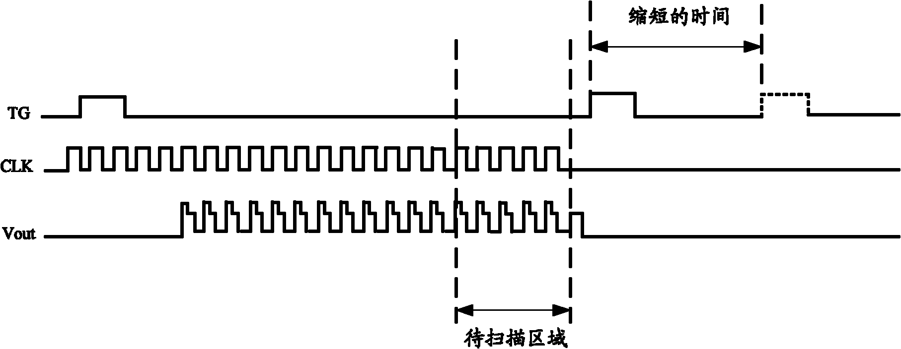
[0038] When the light emitted by the light source irradiates the scanning original, reflection or transmission occurs on the scanning original, and the generated reflected light or transmitted light is transmitted to the photoelectric conversion component through the optical path, and the photosensitive unit in the photoelectric conversion component performs photoelectricity on the received light. In c...


PUM


Abstract

The invention discloses a scanning method. According to the drop location of a scanned original copy and width of an area to be scanned, a sensitive unit in a photoelectric conversion component is divided into a front section, a middle section and a rear section; after the photoelectric conversion component carries out photelectric conversion on the received light ray, only exposure voltage signals which are generated in the sensitive unit positioned at the front section and the middle section are output, thus the time of signal output by the photoelectric conversion component is shortened, and on the premises of ensuring the scanning quality, the scanning time is shortened. The invention also discloses a scanning device and a scanner.

Description

technical field [0001] The invention belongs to the technical field of scanners, and in particular relates to a scanning method, a scanning device and a scanner. Background technique [0002] The scanner is mainly composed of four parts: optical system, photoelectric conversion component, electronic system and mechanical system. The optical system is mainly composed of a light source, some reflectors and prisms. Its function is to irradiate the light emitted by the light source on the scanning original, and then focus the light through the prism to the photoelectric conversion component through the optical path. The photoelectric conversion component includes a plurality of photosensitive units arranged in a row (the distribution direction of the photosensitive elements is recorded as the X direction). The photoelectric conversion component can use a charge-coupled device (CCD) or a contact image sensor (CIS), and its function is to convert light to The signal is converted ...

Claims


Application Information

Patent Timeline
Patent Type & Authority Applications(China)
IPC IPC(8): H04N1/04H04N1/047H04N1/028
Inventor 何建贤刘翰纶
Owner QISDA SUZHOU
Why Eureka
Try Eureka