Intake system structure of power unit

A technology of power unit and system structure, applied in the direction of charging system, engine components, engine control, etc., can solve the problems of rotational position deviation of the fastening part, complex connection operation, complex structure, etc., to reduce the protrusion in the height direction, The effect of improving workability and suppressing space

Active Publication Date: 2013-05-22
HONDA MOTOR CO LTD
View PDF1 Cites 0 Cited by
  • Summary
  • Abstract
  • Description
  • Claims
  • Application Information

AI Technical Summary

Problems solved by technology

[0004] However, as shown in the aforementioned Patent Document 1, for example, in a power unit in which the air cleaner is disposed at a position separated from the cylinder portion of the internal combustion engine and the throttle region is disposed at a position close to the cylinder portion, the connecting pipe is generally relatively long. Components that are prone to deviations in the rotational position around the pipe axis in the fastening portion during installation
If tightening is performed when there is deviation in alignment in the direction of rotation, shape deformation, etc., may occur due to torsional stress.
[0005] In addition, in order to accurately perform such alignment, a complicated structure and complicated connection work are required.

Method used


Image

  • Intake system structure of power unit
  • Intake system structure of power unit
  • Intake system structure of power unit

Examples


Embodiment Construction

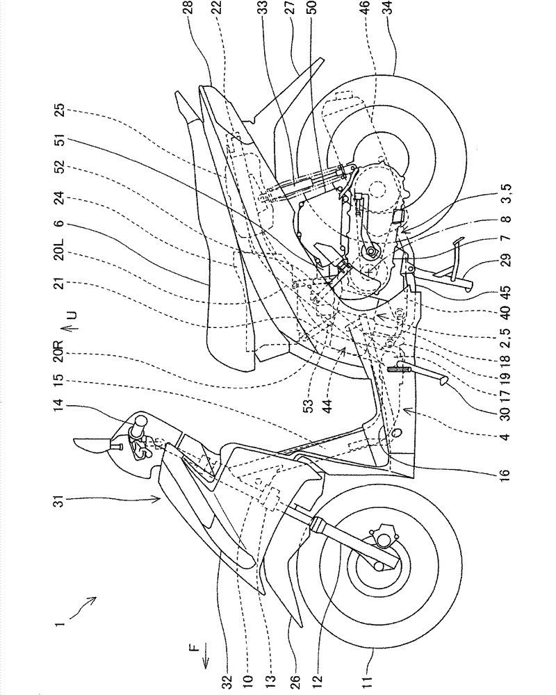
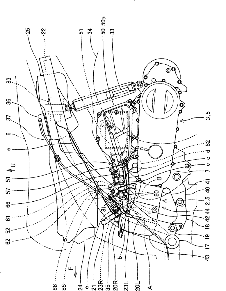
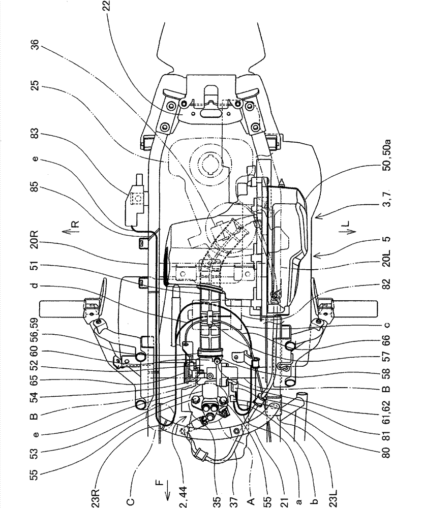
[0089] Below, refer to Figure 1 to Figure 9 , the configuration of the air intake system of the power unit according to the embodiment of the present invention will be described.

[0090] It should be noted that directions such as front, rear, left, right, up and down in the description of this specification and the claims refer to the directions of a vehicle in which the power unit according to this embodiment is mounted on a vehicle, particularly a small vehicle such as a motorcycle. direction. In the figure, arrow F indicates the front of the vehicle, L indicates the left side of the vehicle, R indicates the right side of the vehicle, and U indicates the upper side of the vehicle.

[0091] In addition, in the drawings, hollow arrows schematically indicate the flow of intake air to the internal combustion engine, small arrows m schematically indicate the flow of idle air, and small arrows n schematically indicate the flow of bypass air at startup.

[0092] figure 1 The ...


PUM


Abstract

This intake system structure of a power unit (5), which is mounted to a vehicle (1), and in which an internal combustion engine (2) and a power transmission 3 are integrated with each other, an air cleaner (50) is provided at a position away from a cylinder part (44) of the internal combustion engine (2), a throttle body (52) is disposed at a position close to the cylinder part, and the air cleaner and the throttle body are connected to each other by a connecting tube (51), wherein a regulating member (54) around the axis of an intake passage (52a) regulates the throttle body (52) in a position in the rotating direction around the axis with respect to the cylinder part, the throttle body is assembled to the cylinder part through an inlet manifold (53) and supported integrally, and in the throttle body, a connecting cylindrical part (60) to the connecting tube is provided with a positioning part (61) for positioning the connecting tube in the rotating direction.

Description

technical field [0001] The present invention relates to an air intake system structure of a power unit equipped with an internal combustion engine mounted on a vehicle, particularly a small vehicle. Background technique [0002] At present, in the air intake system of a power unit integrated with an internal combustion engine and a power transmission device mounted on a vehicle, especially a small vehicle, as shown in the following patent document 1, the throttle valve area is provided with the internal combustion engine and the air filter. Between the cleaners, the throttle area is connected to the air filter through a connecting pipe. In addition, the downstream end of the connecting pipe is fixedly supported by fastening the periphery of the upstream inlet portion in which the throttle valve region is fitted in the downstream end of the connecting pipe with a fastening band. [0003] Patent Document 1: Japanese Unexamined Patent Publication No. 2006-291777 ( figure 2 , ...

Claims


Application Information

Patent Timeline
Patent Type & Authority Patents(China)
IPC IPC(8): F02M35/10F02D9/02F02D9/10
CPCF02M35/162F02M35/10216F02M35/10039F02M35/10078F02M35/10144
Inventor 池田健一郎箕轮和也洼田俊行
Owner HONDA MOTOR CO LTD
Why Eureka
Try Eureka