A Fiber Bragg Grating Temperature Sensor

A technology of temperature sensor and optical fiber grating, which is applied in thermometers, thermometers with physical/chemical changes, instruments, etc., can solve the problem that the optical fiber grating temperature sensor cannot have strong protection strength and response speed at the same time, so as to achieve easy implementation and strong protection The effect of strength and simple package structure

Active Publication Date: 2016-04-06
SHANGHAI KNP CHEM +1
View PDF5 Cites 1 Cited by
  • Summary
  • Abstract
  • Description
  • Claims
  • Application Information

AI Technical Summary

Problems solved by technology

[0004] The purpose of the present invention is to solve the technical problem that the fiber grating temperature sensor in the prior art cannot have strong protection strength and fast response speed at the same time, and to provide a kind of protection strength that not only has strong protection strength, but also can protect the environment temperature. Fast Response Fiber Bragg Grating Temperature Sensor

Method used


Image

  • A Fiber Bragg Grating Temperature Sensor
  • A Fiber Bragg Grating Temperature Sensor
  • A Fiber Bragg Grating Temperature Sensor

Examples


Embodiment 1

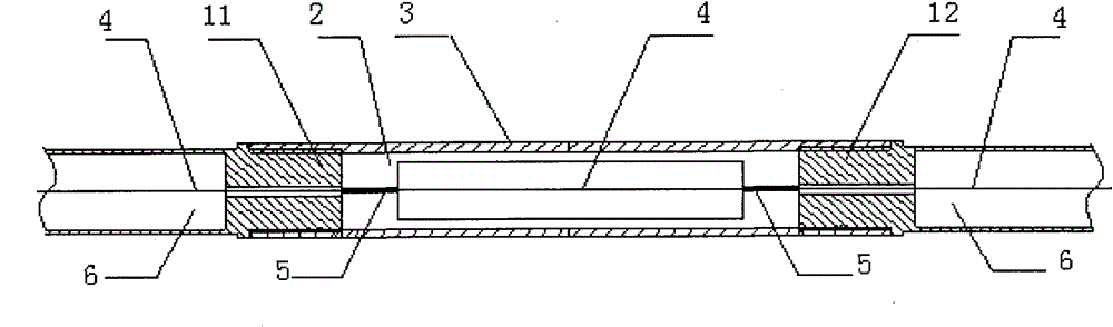
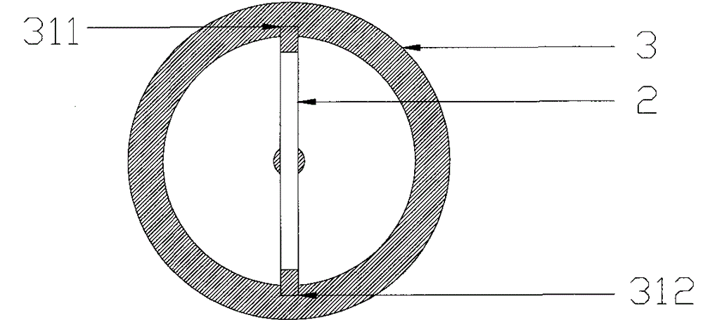
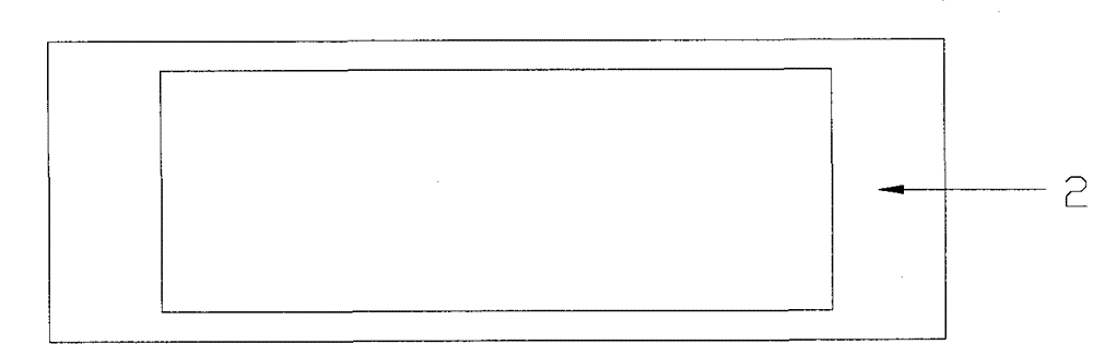
[0019] Example 1: Please also refer to Figure 1 to Figure 3 , figure 1 It is a structural schematic diagram of the first embodiment of the present invention; figure 2 yes figure 1 side view of the sectional view; image 3 It is a schematic diagram of the structure of a rectangular optical fiber fixing sheet. As shown in the figure, the fiber grating temperature sensor includes a fiber grating 4, an optical fiber fixing piece 2 for fixing the fiber grating 4, the fiber fixing piece 2 is built into the packaging tube 3, and two optical cable connectors with a through hole in the center of the cross section 11, 12 are connected with the two ends of the packaging tube 3, and the two ends of the fiber grating 4 fixed on the optical fiber fixing sheet 2 are respectively passed through the through holes in the two optical cable connectors 11, 12, and connected to the optical cable 6. connect.

[0020] Two grooves 311, 312 are arranged axially symmetrically on the inner wall of...

Embodiment 2

[0024] Example 2: Please also refer to Figure 4 to Figure 6 , Figure 4 It is a structural schematic diagram of the second embodiment of the present invention; Figure 5 yes Figure 4 side view of the sectional view; Figure 6 It is a structural schematic diagram of a dumbbell-shaped optical fiber fixing sheet. The difference between embodiment 2 and embodiment 1 is that the fiber fixing sheet 2 used in embodiment 2 is dumbbell-shaped, and the fiber grating 4 is fixed to the fixed parts 5 at both ends of the fiber fixing sheet 2 by gluing or welding. place, such as Figure 4 As shown, the two ends of the fiber fixing sheet 2 are inserted into the two grooves 311, 312 of the packaging tube 3, and the middle parts of the fiber fixing sheet 2 and the fiber grating 4 are placed inside the cavity of the packaging tube 3. Since the fiber fixing sheet 2 is dumbbell-shaped, and the upper and lower edges of the middle part are not in contact with the packaging tube 3, that is, th...


PUM


Abstract

The invention discloses an optical fiber grating temperature sensor, which comprises an optical fiber grating, an optical fiber fixing sheet for fixing the optical fiber grating, the optical fiber fixing sheet is built into a packaging tube, and two optical cable connectors with a through hole opened in the center of the cross section along the axial direction are connected to the At both ends of the packaging tube, the fiber fixing piece is located between the two optical cable connectors, and the fiber gratings fixed on the fiber fixing piece respectively pass through the through holes of the two optical cable connectors. The fiber grating temperature sensor adopting this packaging structure, on the one hand, the packaging tube has a certain thickness and strength, and the packaging through the packaging tube ensures a strong protection for the fiber grating; on the other hand, the temperature of the fiber grating is greatly improved. The sensor's response speed to ambient temperature. At the same time, the packaging structure of the fiber grating temperature sensor is simple and compact, and is convenient for implementation.

Description

technical field [0001] The invention relates to the field of temperature sensors, in particular to the field of fiber grating temperature sensors. Background technique [0002] At present, temperature sensors are widely used in various engineering structures, such as tunnels, bridges, embankments, and large buildings, for construction monitoring, long-term health monitoring, and fire detection. Traditional temperature sensors have disadvantages such as low precision, susceptibility to electromagnetic interference, poor stability, and short signal transmission distance, making it difficult to perform accurate monitoring in harsh working environments. Compared with the traditional temperature sensor, the fiber grating temperature sensor has the advantages of high sensitivity, small size, light weight, safety explosion-proof, strong anti-electromagnetic interference ability, and long signal transmission distance. Therefore, the fiber grating temperature sensor is more and more ...

Claims


Application Information

Patent Timeline
Patent Type & Authority Patents(China)
IPC IPC(8): G01K11/32G02B6/38G01K11/3206
Inventor 张杰钱洪卫夏懋寅陆宗源何唯平
Owner SHANGHAI KNP CHEM
Why Eureka
Try Eureka