
Liquid container, liquid supply device and image printing device
A liquid container and liquid supply technology, which is applied in printing and other directions, can solve the problems of no longer effective, reduction, and inability to elastically return deformation, and achieve the effect of opportunity reduction
- Summary
- Abstract
- Description
- Claims
- Application Information
AI Technical Summary
Problems solved by technology
Method used
Image

Examples
Embodiment Construction
[0032] available by reference Figure 1-15 To understand the embodiments of the present invention, as well as other features and advantages, like reference numerals are used for corresponding parts in the various figures.
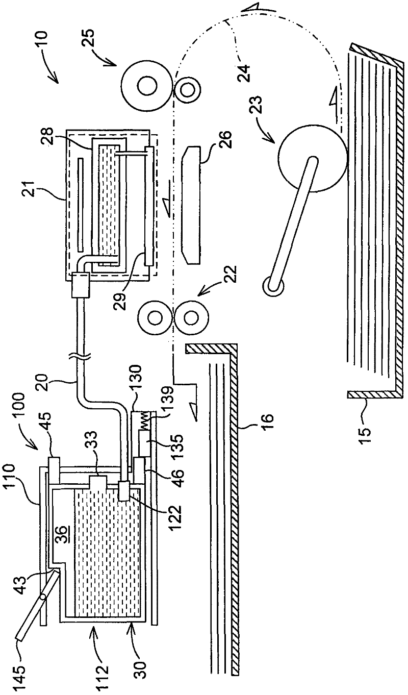
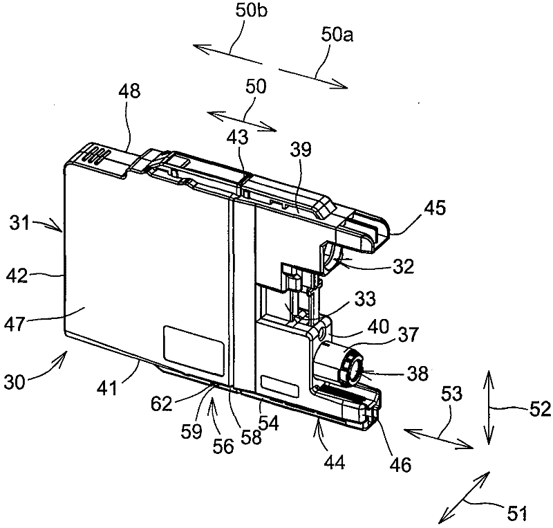
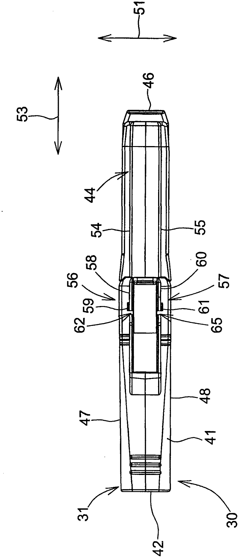
[0033] refer to figure 1 , the printer 10 is configured to print an image by selectively ejecting ink droplets on printing paper. The printer 10 includes an ink supply device 100 . The ink supply device 100 includes a mounting part 110 . The mounting portion 110 allows the ink cartridge 30 to be mounted therein. The mounting part 110 has an opening 112 , and the inside of the mounting part 110 is configured to be exposed to the outside of the mounting part 110 through the opening 112 . The ink cartridge 30 is configured to be inserted along the insertion direction 50a via the opening 112 (see figure 2 ) is inserted into the mounting portion 110 to be mounted in the mounting portion 110. The ink cartridge 30 is also configured to be removed via the op...
PUM
 Abstract
Description
Claims
Application Information