Fuel pump

A fuel pump and fuel injection technology, applied in the field of low pressure pump and fuel pump, can solve problems such as unfavorable flow ratio, achieve the effect of simple structure and improved working mode

Active Publication Date: 2012-01-18
ROBERT BOSCH GMBH
View PDF6 Cites 0 Cited by
  • Summary
  • Abstract
  • Description
  • Claims
  • Application Information

AI Technical Summary

Problems solved by technology

However, the problem arises here that, on the one hand, a compact configuration is desirable, but on the other hand, unfavorable flow ratios arise

Method used


Image

  • Fuel pump
  • Fuel pump
  • Fuel pump

Examples


Embodiment Construction

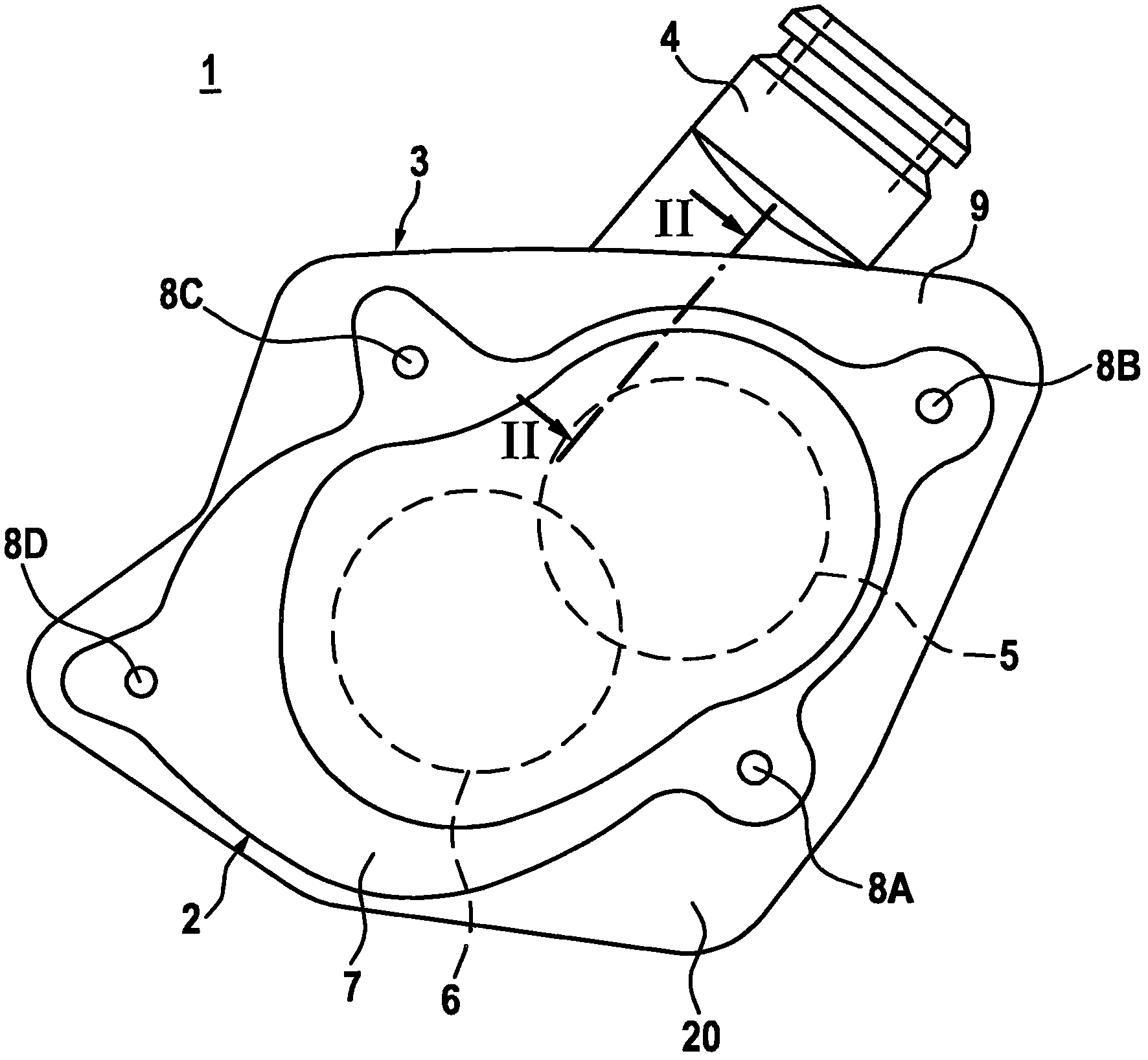
[0019] figure 1 A side view of a fuel pump 1 according to one embodiment of the invention is shown. The fuel pump 1 may in particular be designed as a pump device for a fuel injection system of an air-compressed self-ignition internal combustion engine with a low-pressure pump, for example an external gear pump 2 , and a high-pressure pump 3 . The fuel pump 1 can also be designed as another gear pump, in particular an internal gear pump, or as a vane pump. A preferred application of the fuel pump 1 is in a fuel injection system with a fuel distribution rail, which stores diesel fuel at high pressure. However, the fuel pump 1 according to the invention is also suitable for other applications.

[0020] The fuel pump 1 of this exemplary embodiment has a first pump part 2 designed as an external gear pump 2 and a second pump part 3 designed as a high-pressure pump 3 . In this case, the second pump part 3 is located behind the first pump part 2 in the side view shown and is part...


PUM


Abstract

The invention relates to a fuel pump (1) serving in particular as a vacuum pump for a pump arrangement having a vacuum pump and a high-pressure pump for fuel injection systems of turbocharged compression-ignition internal combustion engines, comprising an inlet channel (15) and a connecting channel (19) on the suction side thereof. The connecting channel (19) thereby runs in a direction (22) deviating from a direction (16) of the inlet channel (15). A throttle (30) is further provided, wherein the throttle (30) connects to the inlet channel (15) in the direction (16) of the inlet channel (15) and opens into the connecting channel (19) on the side. A reliable throttle effect is thus provided, in order to allow vacuum-throttled operation of the fuel pump.

Description

technical field [0001] The invention relates to a fuel pump, in particular to a low-pressure pump of a pump arrangement having a low-pressure pump and a high-pressure pump. In particular, the invention relates to the field of fuel injection devices for air-compressed self-ignition internal combustion engines. Background technique [0002] DE 197 36 160 A1 discloses a pump device for supplying fuel with high pressure in a fuel injection system of an internal combustion engine. The known pump device is particularly suitable for common rail injection systems. The known pump arrangement comprises a radial piston pump with a drive shaft mounted in a pump housing and a low-pressure pump connected upstream of the radial piston pump. The delivery of fuel from the low-pressure pump to the high-pressure pump takes place via bores in the pump housing (monolithic block). The suction connection is located on the pump housing here. [0003] It is conceivable to provide a throttle in t...

Claims


Application Information

Patent Timeline
Patent Type & Authority Applications(China)
IPC IPC(8): F04B23/10F02M55/04
CPCF02M59/44F04B53/16F04B1/0404F04B23/103F04B23/12
Inventor M·克里斯滕A·默茨M·格里布
Owner ROBERT BOSCH GMBH
Why Eureka
Try Eureka