Test circuit of dynamic reactive power compensation and harmonic control device and test method thereof

A technology of harmonic control and test circuit, which is applied in the direction of measuring device, measuring electricity, measuring electric variables, etc.

Inactive Publication Date: 2012-05-02
STATE GRID ZHEJIANG ELECTRIC POWER CO LTD SHAOXING POWER SUPPLY CO +2
View PDF5 Cites 13 Cited by
  • Summary
  • Abstract
  • Description
  • Claims
  • Application Information

AI Technical Summary

Problems solved by technology

[0003] In order to overcome the shortcomings of the existing dynamic reactive power compensation device test methods

Method used


Image

  • Test circuit of dynamic reactive power compensation and harmonic control device and test method thereof
  • Test circuit of dynamic reactive power compensation and harmonic control device and test method thereof

Examples


Embodiment Construction

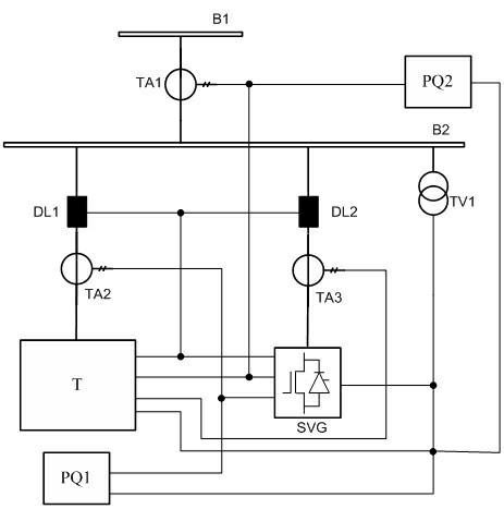
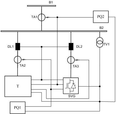
[0011] Such as figure 1 As shown, the test circuit of a dynamic reactive power compensation and harmonic control device in this embodiment adopts a static var generator SVG capable of absorbing reactive power, absorbing harmonic current, and fast response speed as the test object. The equipment of sample T; the static var generator SVG is a device composed of high-power power electronic devices as the core, which can continuously and rapidly emit or absorb reactive power, can emit or absorb harmonic current, and can also emit three-phase unbalanced current . Among them, the main power supply line B1 is connected to the small test bus B2, and the static var generator SVG and the tested product T are connected in parallel to the test small bus B2, so that the static var generator SVG and the tested product T are connected to the same test line. On the small bus B2; the static var generator SVG and the test product T are respectively connected in series with the static var gener...


PUM


Abstract

The invention discloses a test circuit of a dynamic reactive power compensation and harmonic control device and a test method thereof. A static var generator (SVG) is used as a device for testing a test object, wherein a power main inlet wire is connected with a miniature test bus; the SVG is connected with the miniature test bus after being connected the test object in parallel; a SVG branch current transformer and a test object branch current transformer are sequentially connected in series with circuits of the SVG and the test object; a SVG branch grid-connected circuit breaker and a test object grid-connected circuit breaker are also connected in series with the SVG and the test object; and the tripping outlets of the SVG branch grid-connected circuit breaker and test object grid-connected circuit breaker are in parallel connection. The test circuit not only can be used for effectively testing the dynamic adjustment function, filter function and output capacity continuous change function of the tested reactive power compensation device, but also can be used for achieving full-capacity test, temperature rise test and negative sequence compensation capability test of a large-capacity dynamic reactive power compensation device in a system with small power capacity.

Description

technical field [0001] The invention relates to a test circuit and a test method of a dynamic reactive power compensation and harmonic control device in a power system, and is especially suitable for the dynamic compensation device with a voltage level above 3kV to be tested in a manufacturing plant or a test center with a limited total incoming power supply capacity. Product functional performance testing. Background technique [0002] At present, new types of dynamic reactive power compensation and harmonic control devices (hereinafter referred to as tested products) continue to emerge, which can continuously emit or absorb reactive power in function, and some tested products can also emit harmonic current or filter harmonic current . The traditional reactive power compensation device test uses a parallel capacitor bank or a reactor bank to offset the reactive power of the device under test, which cannot verify the dynamic adjustment function, filtering function, and cont...

Claims


Application Information

Patent Timeline
IPC IPC(8): G01R31/00
Inventor 黄祥伟陈晓宇陈远华蔡重凯吴育华李电秋勇金百荣洪金琪吕丹
Owner STATE GRID ZHEJIANG ELECTRIC POWER CO LTD SHAOXING POWER SUPPLY CO
Why Eureka
Try Eureka