Connector

一种连接器、连接部的技术,应用在连接、车辆连接器、连接绝缘等方向,能够解决弹簧垫片202弹压力减弱、产生应力、难以长期维持端子210和对方侧连接器的端子连接可靠性等问题,达到节省收容空间的效果

Active Publication Date: 2012-05-09
YAZAKI CORP
View PDF5 Cites 33 Cited by
  • Summary
  • Abstract
  • Description
  • Claims
  • Application Information

AI Technical Summary

Problems solved by technology

[0010] However, since the floating connector 201 disclosed as a waiting connector in Patent Document 1 is fitted with the counterpart connector, since the inner case 204 and the terminal 210 move, the electric wire 207 connected to the terminal 210 also moves. Stress may be generated on the electrical parts connected to the electric wires 207, or the connection reliability between the electric wires 207 and the electrical parts may be reduced.
[0011] In addition, because the floating connector 201 disclosed as a waiting connector in Patent Document 1 is configured to maintain the connection between the terminal 210 and the terminal of the counterpart side connector only by the biasing force of the spring washer 202, that is, the elastic force, Therefore, it is considered that due to the aging of the spring washer 202 and the attenuation of the elastic force, the spring force of the spring washer 202 is weakened, and there is a problem that it is difficult to maintain the connection reliability between the terminal 210 and the terminal of the counterpart connector for a long time.

Method used


Image

  • Connector
  • Connector
  • Connector

Examples


Embodiment Construction

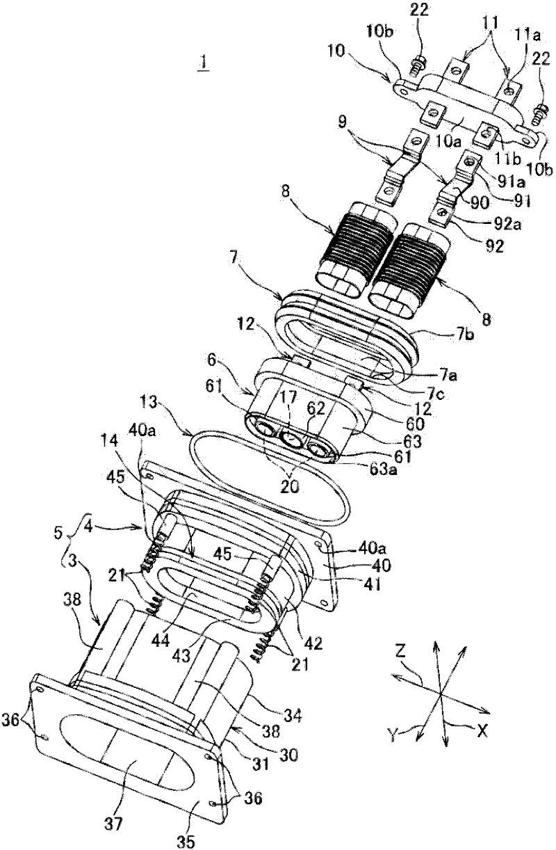
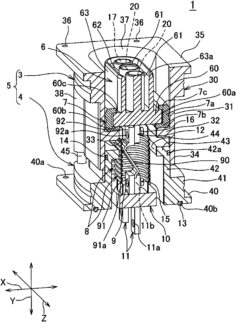
[0047] Below, refer to Figure 1 to Figure 11 , while describing a connector according to one embodiment of the present invention.

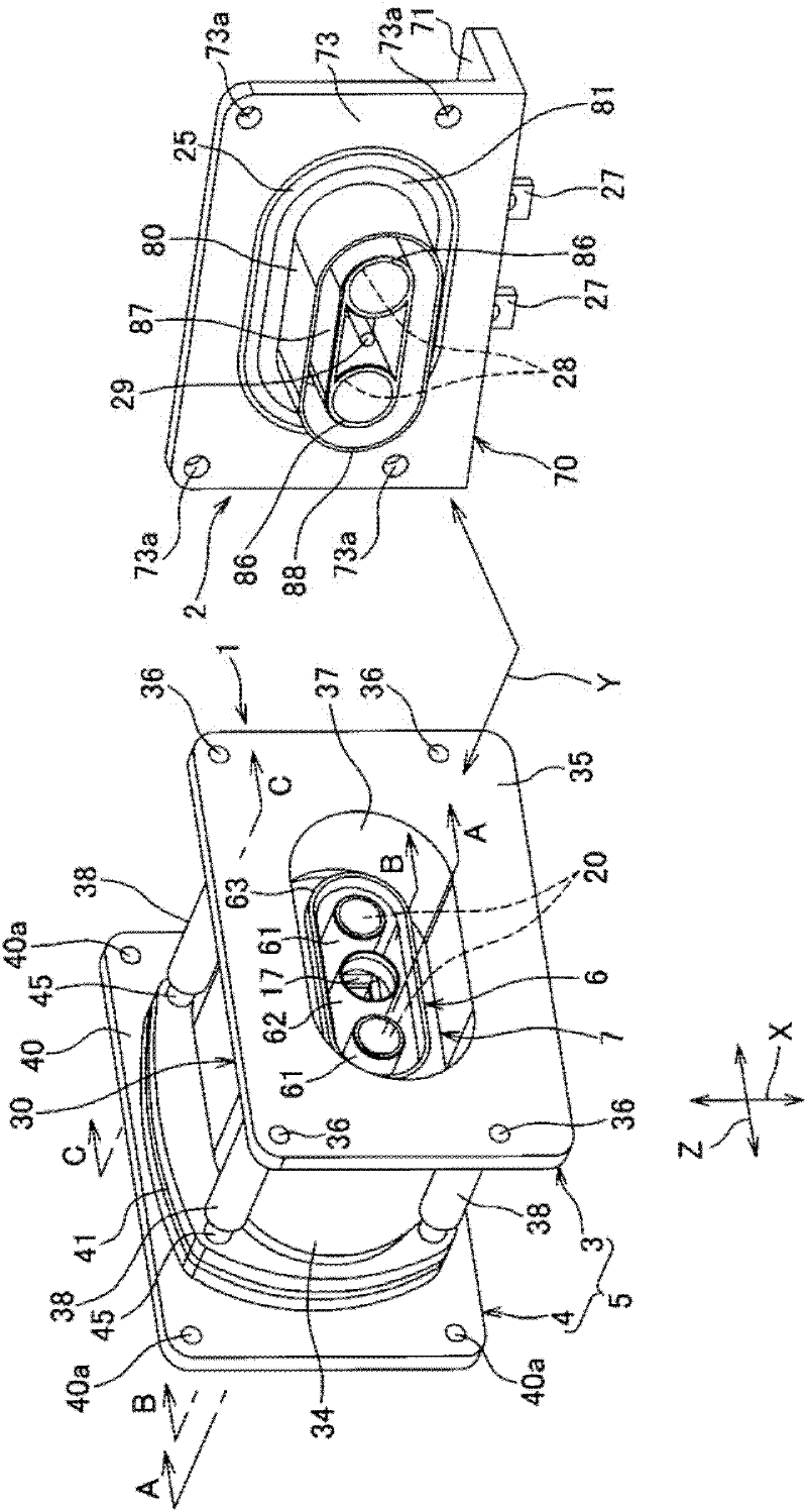
[0048] The connector 1 of the present invention is a standby connector mounted on an inverter case mounted on an automobile and electrically connected to a counterpart connector 2 mounted on a motor case. That is, the connector 1 is a standby connector that is directly connected to the counterpart connector 2 provided integrally with the motor when the inverter is mounted on the motor.

[0049] in addition, figure 1 Arrow Y in the diagram indicates the mating direction of the mating connector 2 and the connector 1 , and arrow X indicates the width direction of the connector 1 in a direction perpendicular to the mating direction. In addition, arrow Z indicates the longitudinal direction of the connector 1 in the direction perpendicular to the above-mentioned fitting direction.

[0050] The above counterpart side connector 2 such as figure 1 ...


PUM


Abstract

Provided is a connector which can absorb the position gap with respect to a counterpart connector, and can maintain an excellent connection with an electric circuit within a case to which the connector is attached. The connector (1) connected to a counterpart connector secured to a case of a motor is comprised of an outer housing (5) attached to a case of an inverter; a first inner housing (6) which contains a first terminal (20) engaged with a terminal of the counterpart connector and which is contained in the outer housing (5) so as to move in an engaging direction (Y) of the first terminal (20) and a direction intersecting with the engaging direction (Y) in order to engage with the counterpart connector; a second inner housing (10) which contains a second terminal (11) electrically connected to an electric circuit within the case and which is fixed within the outer housing (5); a connection portion (9) which is composed of a braided electric wire (90) and which electrically connects the first terminal (20) to the second terminal (11); and a packing (7) attached to the first inner housing (6).

Description

technical field [0001] The present invention relates to a connector used for connection and the like between electronic devices. Background technique [0002] Cars are equipped with various electronic devices. Wire harnesses have traditionally been used to connect these electronic devices to each other. The wire harness refers to a component composed of a plurality of electric wires and a plurality of connectors attached to ends of the electric wires. Then, each connector passing through the wire harness is connected to each waiting connector fixed to a case or the like of each electronic device, and these electronic devices are connected to each other. In addition, the standby connector refers to a connector fixed to a panel, a box, or the like. [0003] However, when the above-mentioned electronic devices are connected to each other by a wire harness having large-diameter electric wires such as power cords, since the large-diameter electric wires are difficult to bend, ...

Claims


Application Information

Patent Timeline
Patent Type & Authority Applications(China)
IPC IPC(8): H01R13/631H01R13/52H01R13/621H01R13/533
CPCH01R13/502H01R4/70H01R13/6315H01R13/5219H01R2201/26
Inventor 田代晴纪
Owner YAZAKI CORP
Why Eureka
Try Eureka