High-efficiency hand-driven dewaterer

A driving type dehydrator technology, applied in the field of high-efficiency hand-driven dehydrators, can solve the problems of wasting electric energy and inconvenient use, and achieve the effect of simple structure and cost reduction.

Inactive Publication Date: 2012-07-04
顾王建
View PDF5 Cites 0 Cited by
  • Summary
  • Abstract
  • Description
  • Claims
  • Application Information

AI Technical Summary

Problems solved by technology

[0004] The purpose of the present invention is to provide a high-efficiency hand-driven dehydrator, which solves the problems of wasting electric energy and inconvenient use of the existing dehydrator

Method used


Image

  • High-efficiency hand-driven dewaterer
  • High-efficiency hand-driven dewaterer
  • High-efficiency hand-driven dewaterer

Examples


Embodiment Construction

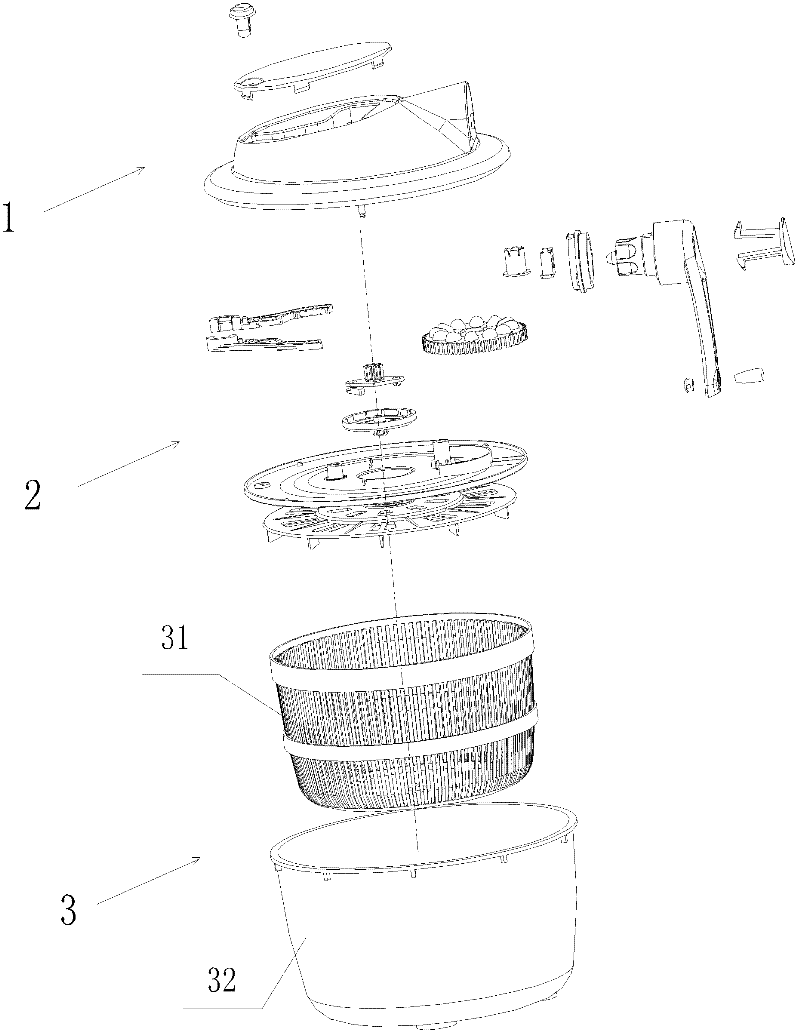
[0017] refer to figure 1 , The dehydrator of the present invention is composed of top protection device 1, hand-operated driving device 2 and dehydration device 3 from top to bottom.

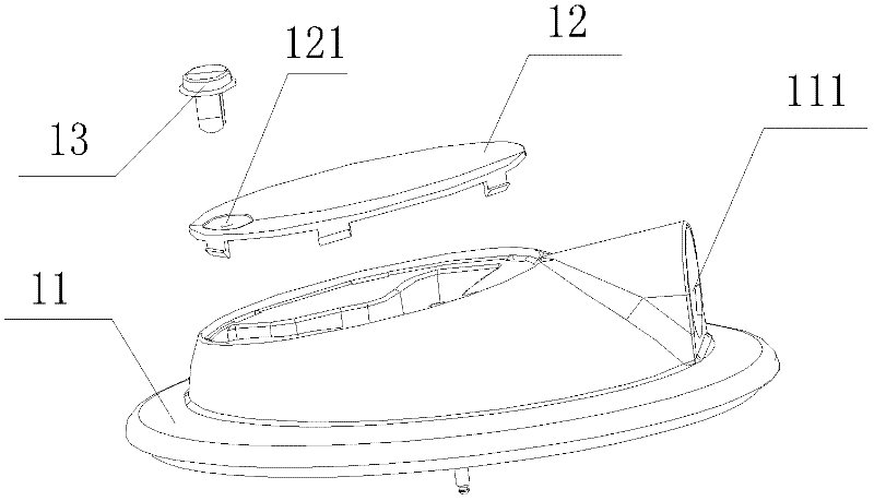
[0018] refer to figure 2 , the support of the top protection device 1 is a top cap 11, and a rocker installation hole 111 fixed by a rocker installation ring 253 is formed on the edge of the top cap, a top cover 12 is installed on the top of the top cap 11, and a A button mounting hole 121 for the brake button 13 to be installed.

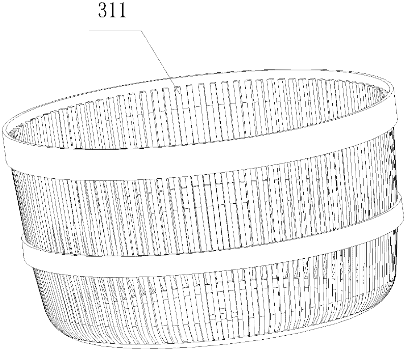
[0019] refer to figure 1 and image 3 , the dehydration device 3 comprises a dehydration basket 31 and a dehydration bucket 32, the dehydration basket 31 is located in the dehydration bucket 32 ​​and is fixed thereto, the basket wall of the dehydration basket (31) is made into a grid shape, and its grid bars (311) protrude inwardly , the dehydration barrel 32 bottoms are shaped on a through hole for drainage.

[0020] refer to Figure 4 , The hand-operated driv...


PUM


Abstract

The invention relates to a high-efficiency hand-driven dewaterer. A top protection device is arranged at the lower part of the high-efficiency hand-driven dewaterer. A dewatering device is arranged at the lower part of the high-efficiency hand-driven dewaterer. A hand-driven power system which consists of a handle device, a reversing device, a one-way rotation control device and a brake device is arranged between the top protection device and the dewatering device. A plurality of grooves are manufactured on the handle of the handle device. Convex blocks which are structurally matched with the grooves on the handle are manufactured on the upper surface of a reversing gear plate. A one-way controller which is structurally matched with a one-way turntable is arranged on the one-way turntable, wherein a plurality of clamping bulges are formed on the inner wall of the one-way turntable. The brake device consists of a brake caliper and a brake button which is installed on a top cover. Since the hand-driven power system is used as a power source to replace the original motor, the goal of energy saving is achieved; and since the one-way rotation control device and the brake device are arranged in the hand-driven power system, not only can dehydration be continuously conducted after the handle is stopped from being turned, but also the dehydration device can be rapidly stopped from rotating according to the need and a user can conveniently take out dehydrated and washed clothes in time.

Description

[0001] The present invention is a divisional application whose application number is 200910100061.4, the application date is June 22, 2009, and the invention name is a hand-operated dehydrator. technical field [0002] The invention relates to a dehydrator, in particular to a high-efficiency hand-driven dehydrator. Background technique [0003] At present, there are many kinds of dehydrators on the market. They are relatively complete in structure and function, but these dehydrators all use electric motors as power sources, which is not suitable for applications today when energy is relatively tight, especially for small pieces of clothing or washing. Clean vegetable dehydration is a waste of electric energy; the use of motor dehydrators is also limited in time and space, and it must be near the power supply and can be used normally when the power supply is guaranteed, which brings great inconvenience to life. Contents of the invention [0004] The purpose of the present i...

Claims


Application Information

Patent Timeline
Patent Type & Authority Applications(China)
IPC IPC(8): F26B11/08
Inventor 顾王建
Owner 顾王建
Why Eureka
Try Eureka