Paper thickness detection device

A technology for thickness detection and paper, which is applied in the field of paper thickness detection devices, and can solve problems such as inability to detect thickness, errors, shaking of detection rollers, etc.

Active Publication Date: 2012-07-04
GLORY KOGYO KK
View PDF6 Cites 13 Cited by
  • Summary
  • Abstract
  • Description
  • Claims
  • Application Information

AI Technical Summary

Problems solved by technology

[0008] However, in the conventional art described above, it is extremely difficult to set the gap d between the detection roller 102 and the reference roller 101.
In addition, even if the above-mentioned gap d can be set correctly, errors may gradually occur during use.
[0009] In addition, in the conventional technology, the detection roller is always in contact with the reference roller, but if the detection roller is always in contact with the reference roller, there is a problem that the detection roller is shaken (pitching) while the paper is passing, and the thickness cannot be accurately detected.
[0010] In addition, if the paper passes between the detection roller and the reference roller, fine dust adhering to the surface of the paper adheres to the detection roller and the reference roller, and if the dust accumulates on the roller, there is a problem that the correct thickness cannot be detected.
Regarding this problem, a scraper (scraper) for removing foreign matter is disclosed in Japanese Patent Laid-Open No. 10-283520, but if the scraper is fixed on a part of the device, even if it is an elastic scraper, it will be damaged by scraping. The front end of the plate hinders the operation of the bill when it protrudes into the detection roller, so there is a problem that the correct thickness cannot be detected
[0011] In addition, in the case where a plurality of detection blocks including detection rollers are arranged in a direction perpendicular to the conveyance direction of the paper, and the detection rollers contact the entire surface of the conveyed paper to detect the thickness of the entire surface of the paper, since the paper protrudes When the detection rollers hit all the detection rollers at once, the detection block moves violently due to the collision, and there is a problem that a kick occurs in the obtained detection output waveform.
In addition, there is a problem of paper jams due to the obstruction when the paper protrudes into the detection roller

Method used


Image

  • Paper thickness detection device
  • Paper thickness detection device
  • Paper thickness detection device

Examples


Embodiment Construction

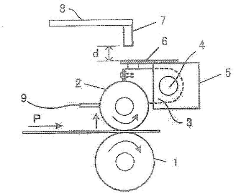
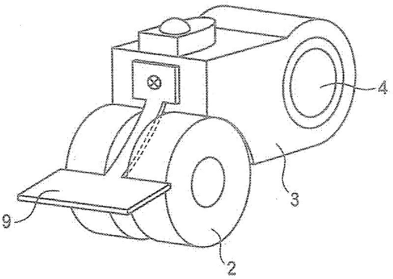
[0031] The paper thickness detection device of the present invention will be described in detail based on the drawings.

[0032] figure 1 It is a diagram for explaining the principle of thickness detection of the paper thickness detection device of the present invention, which includes: a reference roller 1, whose rotating shaft is fixed and used as a criterion for determining the thickness; a detection roller 2, which is set in contact with the reference roller 1; The block 3 is provided with a detection roller 2 at one end, and the other end is rotatably fixed around the support shaft 4, and moves in the direction of the arrow according to the thickness of the paper P passing between the reference roller 1 and the detection roller 2. Position; holding block 5, at least holding the support shaft 4 of the detection block 3; metal leaf spring 6, fixed on the holding block 5, pressing a part of the detection block 3 to maintain the tightness between the detection roller 2 and t...


PUM


Abstract

The invention relates to a paper thickness detection device, which is characterized by comprising a reference roller, a plurality of detection rollers, a detection block, a maintaining block, a first press part and a shifting detection part. The reference roller is arranged on a fixed rotating shaft and provides a reference for thickness judgment. The plurality of detection rollers are arranged opposite to the reference roller and contacted with the reference roller. The plurality of detection rollers are arranged on one end portion of the detection block, and the other end of the detection block rotates freely with a bearing shaft as the center to be fixed and rotates and shifts according to the thickness of the paper between the reference roller and the detection rollers. The maintaining block at least maintains the bearing shaft of the detection block. The first press part is fixed on the maintaining block and presses one part of the detection block to maintain tightness between the plurality of detection rollers and the reference roller. The shifting detection part detects the shifting quantity of the detection rollers. A plurality of detection units formed by the plurality of detection rollers, the detection block, the first press part and the shifting detection part are configured on the bearing shaft.

Description

[0001] This application is a divisional application of the following patent application: the application date is August 31, 2007, the application number is 200780100425.8, and the invention name is "Paper Thickness Detection Device". technical field [0002] The present invention relates to a paper thickness detection device for detecting the thickness of a banknote mounted on a banknote identification device in a cash handling machine installed in a bank or the like, for example. Background technique [0003] In a banknote identification device included in a cash handling machine or a device that handles banknotes such as an automatic vending machine, it is important to identify counterfeit banknotes made of tape, paper, etc., and for this reason, a banknote identification device is included. [0004] In particular, in recent years, the counterfeiting technology has become more sophisticated, and for example, there have been technologies for counterfeiting banknotes, securit...

Claims


Application Information

Patent Timeline
IPC IPC(8): G07D7/16B65H7/02G07D7/164
Inventor 村中光彦小川和人
Owner GLORY KOGYO KK
Why Eureka
Try Eureka