Aerial cableway transport installation and method

a technology of aerial cableway and installation method, which is applied in the directions of transportation and packaging, transportation of rope railways, sustainable transportation, etc., can solve the problems of passengers' discomfort, and achieve the effect of improving the comfort of passengers of the vehicles

Active Publication Date: 2017-11-28
POMAGALSKI
View PDF20 Cites 0 Cited by
  • Summary
  • Abstract
  • Description
  • Claims
  • Application Information

AI Technical Summary

Benefits of technology

[0003]One object of the invention consists in providing means for improving the comfort of the passengers of the vehicles during their transport.
[0004]Another object of the invention is to reduce the power consumption of a transport installation by cableway.
[0012]Jerking generated on the rope which occurs when a vehicle on the line passes over a flexing pillar of the aerial cableway is thus reduced. The flexing pillar of the aerial cableway can be a support pillar to flex the rope in a descending direction, or a compression pillar to flex the rope in an ascending direction, or on the other hand a support-compression pillar which acts as a support pillar or a compression pillar. When a vehicle passes over a pillar, the global tension generated on the rope does in fact vary which causes a jerk on the rope. In order to reduce jerking, one or more other vehicles are coupled to the aerial cableway to counteract the variation of the global tension on the rope, either by increasing the tension when the latter tends to decrease, or the opposite. By coupling at least one vehicle in a terminal when another vehicle coupled to the rope passes over a pillar, the torque provided by the drive motor is smoothed in order to limit jerking and reduce the power consumed by the motor. Jerking of the motor can thus be reduced for different configurations of the transport installations, in particular those which have a single support pillar or a single compression pillar. Advantageously the necessary power of the drive motor is reduced. It is thus possible to envisage using a single drive motor having smaller dimensions. According to another advantage, the braking force of the rope is reduced and less powerful brakes can be used for the drive motor and for the bull-wheel. According to another advantage, the necessary power of the drive motor is reduced and it can be envisaged to use a weaker motor shaft inertia.
[0016]In particular, when a vehicle is hauled from a downhill point to an uphill point, when the vehicle passes over a support pillar, it is then hauled from an uphill point to a downhill point, and the vehicle enhances driving of the rope, which leads to jerking of the motor. When the vehicle passes over the support pillar, the rate of variation of the torque becomes higher than a set threshold, and another vehicle is coupled to increase the motor torque again, thereby smoothing the torque supplied by the drive motor of the rope. By means of controlled coupling of the vehicles in the terminal, the motor torque supplied by the motor can be smoothed, which improves passenger comfort and reduces the power consumption of the bull-wheel drive motor. What is meant by rate of variation is the absolute value of the variation, either increasing or decreasing, of the motor torque supplied by the drive motor divided by a duration.

Problems solved by technology

In particular, when the vehicles pass a pillar, jerking may occur due in particular to the change of direction of the rope which modifies the tension exerted on the latter and may cause discomfort for the passengers.

Method used


Image

  • Aerial cableway transport installation and method
  • Aerial cableway transport installation and method
  • Aerial cableway transport installation and method

Examples


Embodiment Construction

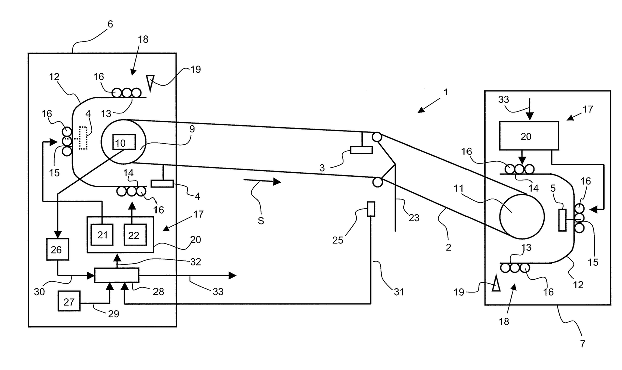
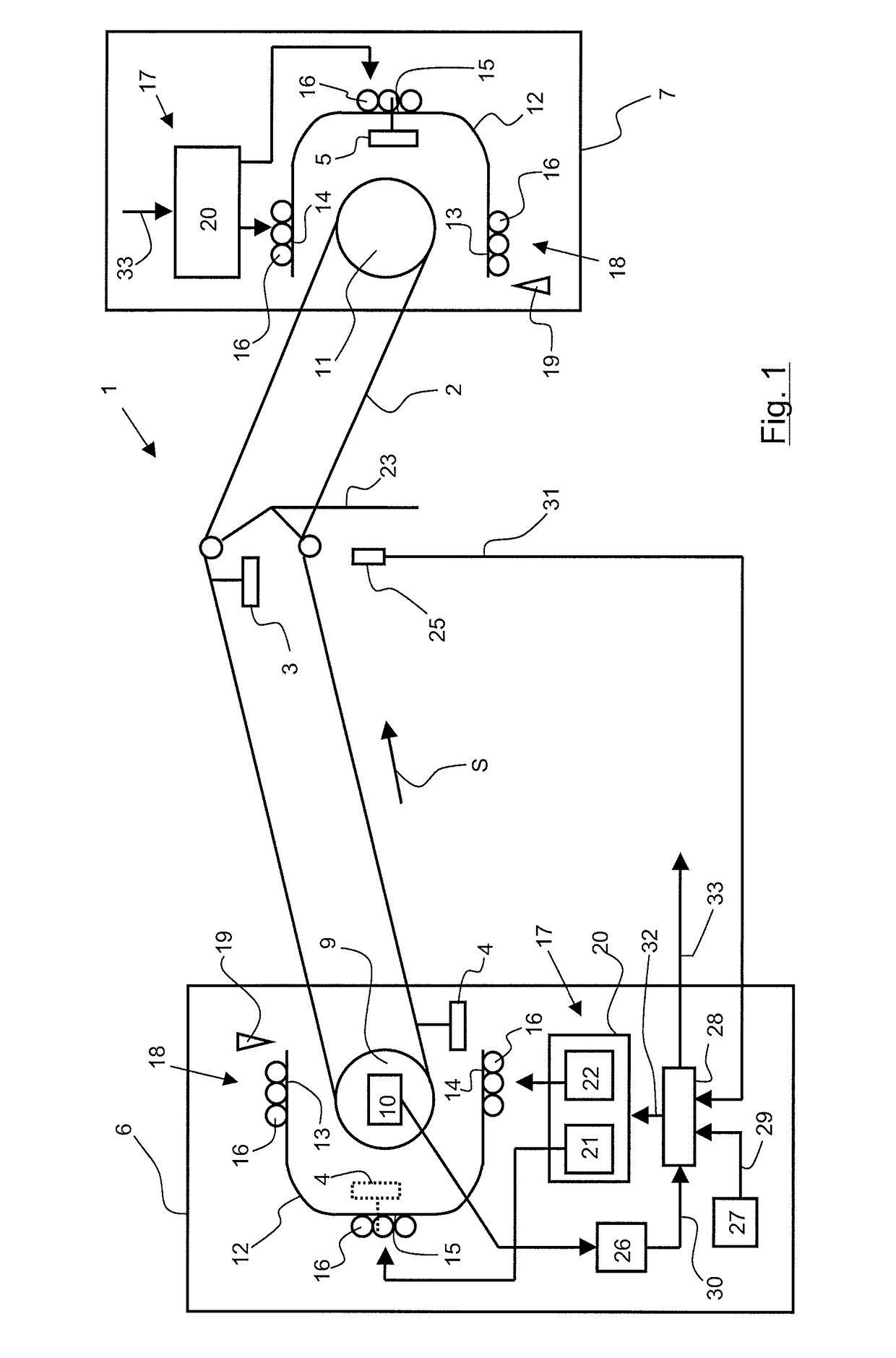
[0040]In FIG. 1, a transport installation 1 by aerial cableway 2 comprising at least two vehicles 3 to 5 has been represented. In the example illustrated in FIG. 1, the installation comprises three vehicles 3 to 5. Vehicles 3 to 5 are configured to be coupled to the rope 2 and hauled by the latter. The transport installation 1 is in general manner a cable car. More particularly, the installation 1 can be a cabin lift and in this case the vehicles are closed, or it can be a chair lift where the vehicles are open. The installation 1 comprises at least two terminal stations, called terminals 6, 7, for loading and unloading of people. In the examples illustrated in FIGS. 1 and 5, the installation 1 comprises two terminals 6, 7 situated at the same level, i.e. on the same horizontal line. As a variant, a first terminal 6 is located uphill and is called uphill terminal, and a second terminal 7 is located downhill and is called downhill terminal, as illustrated in FIGS. 3 and 4. The transp...


PUM


Abstract

An aerial cableway transport installation, comprising:two vehicles each equipped with a detachable clamp to detach the vehicle from and couple the vehicle to the aerial cableway;one coupling device of the vehicles to the aerial cableway;one flexing pillar of the aerial cableway;detection means of a first vehicle coupled to the aerial cableway passing over said pillar, the detection means being configured to transmit at least one coupling signal when passing is detected; andcontrol means of said coupling device connected to the detection means and configured to command coupling of at least a second vehicle to the aerial cableway on receipt of said coupling signal.

Description

BACKGROUND OF THE INVENTION[0001]The invention relates to transport by aerial cableway, in particular transport of persons, in particular cable cars.STATE OF THE ART[0002]Different types of transport installation by cableway exist at the present time. For example installations which use a hauling rope located at ground level, such as funicular railways. Other installations use one or more aerial hauling ropes, such as cable cars which are transport installations to move one or more passenger vehicles, also called cabins, cars, chairs, etc. Certain cable cars are said to be detachable, i.e. the vehicles designed to be coupled to the aerial hauling rope are provided with a detachable clamp which enables them to be detached from the rope, in particular when they enter a terminal of the installation. Furthermore, these cable cars being designed to transport passengers, it is advantageous to provide means for improving the comfort of the passengers during their transport. In particular, ...

Claims


Application Information

Patent Timeline
Patent Type & Authority Patents(United States)
IPC IPC(8): B61B7/00B61B12/06B61B7/04
CPCB61B7/04B61B12/06Y02T30/30B61B12/04Y02T30/00
Inventor BABAZ, MATHIEU
Owner POMAGALSKI
Why Eureka
Try Eureka