Split clutch

A clutch and split-type technology, applied in the direction of clutches, magnetic drive clutches, non-mechanical drive clutches, etc., can solve the problems of large machining allowance, difficulty, long forging length, etc., and achieve reasonable structure design, easy grasp of size, and cutting process easy effect

Inactive Publication Date: 2012-07-11
广德力达电气有限公司
View PDF5 Cites 3 Cited by
  • Summary
  • Abstract
  • Description
  • Claims
  • Application Information

AI Technical Summary

Problems solved by technology

[0004] In the prior art, die forging is generally used for the baffle plate of ordinary clutches. Because there is a step for installing bearings behind it, the forging length is long, the weight is large, and the machining allowance is large, resulting in material waste and processing difficulties, and the size requirements are also difficult. Mastery, affecting product quality

Method used


Image

  • Split clutch
  • Split clutch

Examples


Embodiment Construction

[0011] In order to make the technical means, creative features, goals and effects achieved by the present invention easy to understand, the present invention will be further described below in conjunction with specific illustrations.

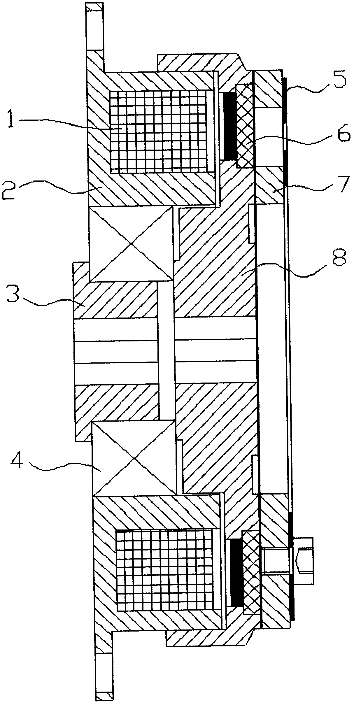
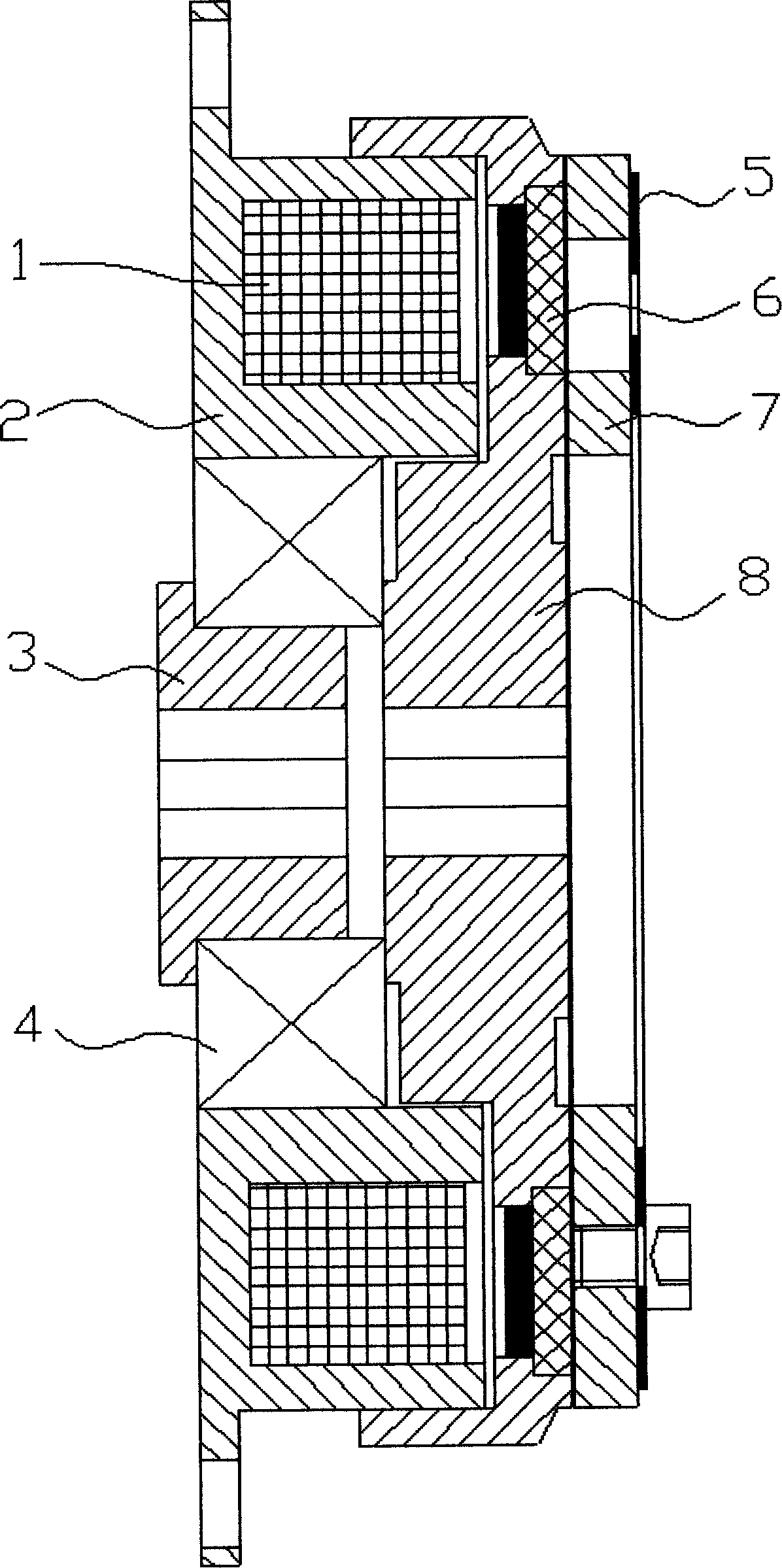
[0012] Such as figure 1 As shown, the split clutch includes a yoke 2, a coil 1 is arranged inside the yoke 2, a baffle 8 is arranged on the right side of the coil 1, a friction plate 6 is arranged on the right side of the baffle 8, an armature 7 is arranged on the right side of the friction plate 6, The right end of the armature 7 is provided with a spring piece 5, the left side of the baffle plate 8 is provided with a bushing 3, the bushing 3 and the baffle plate 8 are coaxially separated, and a bearing 4 is arranged between the bushing 3 and the yoke 2.

[0013] The basic principles, main features and advantages of the present invention have been shown and described above. Those skilled in the industry should understand that the present inven...


PUM


Abstract

A split clutch relates to the technical field of electrical automatic actuators and comprises a magnetic yoke. A coil is arranged in the magnetic yoke, a baffle plate is arranged on the right of the coil, a friction plate is arranged on the right of the baffle plate, an armature is arranged on the right of the friction plate, and a spring sheet is arranged at the right end of the armature. The split clutch is characterized in that a shaft sleeve is arranged on the left of the baffle plate and coaxially split from the baffle plate. The split clutch is reasonable in structural design, a baffle plate of a traditional structure is changed into the baffle plate and the shaft sleeve of the novel structure, forging is facilitated, materials are saved, cutting is simple and convenient, the size of the split clutch is easy to control, and stability of the quality of the split clutch is improved.

Description

Technical field: [0001] The invention relates to the technical field of electrical automation actuators, in particular to a split clutch. Background technique: [0002] The electromagnetic clutch controls the engagement and disengagement of the clutch by turning on and off the electricity of the coil. Electromagnetic clutches can be divided into: dry single-plate electromagnetic clutches, dry multi-plate electromagnetic clutches, wet multi-plate electromagnetic clutches, magnetic powder clutches, slip electromagnetic clutches, etc. [0003] Dry-type single-plate electromagnetic clutch: When the coil is energized, the "armature" piece is magnetically attracted, and the clutch is in the engaged state; when the coil is powered off, the "armature" springs back, and the clutch is in the disengaged state. [0004] In the prior art, die forging is generally used for the baffle plate of ordinary clutches. Because there is a step for installing bearings behind it, the forging length...

Claims


Application Information

Patent Timeline
Patent Type & Authority Applications(China)
IPC IPC(8): F16D27/14
Inventor 李发广曹登明
Owner 广德力达电气有限公司
Why Eureka
Try Eureka