Filtration systems for chemical fluids

A filtration system and fluid technology, applied in the direction of filtration and separation, mining fluid, chemical instruments and methods, etc., can solve the problems of restricting ROV access, cost, time-consuming, etc., and achieve the effect of rapid connection/disconnection

Inactive Publication Date: 2012-07-18
GE OIL & GAS UK LTD
View PDF2 Cites 0 Cited by
  • Summary
  • Abstract
  • Description
  • Claims
  • Application Information

AI Technical Summary

Problems solved by technology

Additionally, the current method of installing filter modules in a horizontal configuration severely limits ROV access
Thus, the current process of MEG filter replacement is difficult, time consuming, and therefore expensive

Method used


Image

  • Filtration systems for chemical fluids
  • Filtration systems for chemical fluids
  • Filtration systems for chemical fluids

Examples


Embodiment Construction

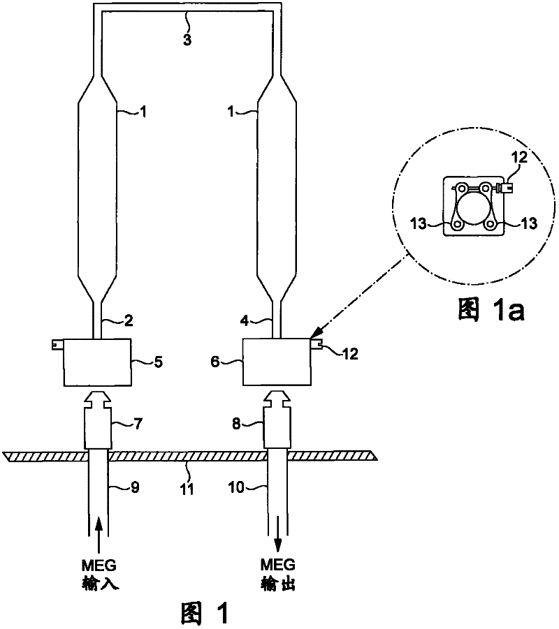
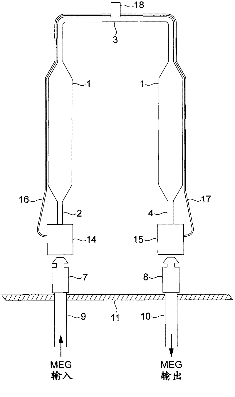
[0015] figure 2 (where, with figure 1 Items in the corresponding items in figure 1 with the same reference numerals in ) shows an application of the invention comprising the introduction of hydraulically operated connectors 14 and 15 in an annular flow line instead of connectors 5 and 6 . As an example, each connector 14 and 15 is a Vetco Gray 21 / 16" flow line hydraulic connector part number A110312-9 used to connect the MEG filter assembly to a semi-permanent base. These connectors require hydraulic actuation hydraulic actuation through hydraulic lines 16 and 17, respectively, at the top of a 180-degree loop to a vertically mounted ROV hot stab connector section 18, which is in the filter on the apex area 3 of the filter assembly. The hydraulic connectors 14 and 15 are self-sealing, preventing seawater ingress and MEG exhaust during filter assembly changes. Each connector has heat from the ROV on two separate circuits. The supply of the entry button hydraulically drives t...


PUM


Abstract

The present invention relates to a filtration systems for chemical fluids. A method of producing a filtration system for filtering a chemical fluid used in a hydrocarbon extraction well comprises providing a filter arrangement (1) having an inlet end (2) and an outlet end (4) and connecting the inlet end to a first fluid flow passageway (9) for the fluid using a first hydraulically operated connector (14) and connecting the outlet end to a second fluid flow passageway (10) using a second hydraulically operated connector (15).

Description

technical field [0001] The present invention relates to filtration systems for chemical fluids, particularly those used in hydrocarbon extraction wells. Background technique [0002] Flow lines and pipelines carrying hydrocarbons are subject to the accumulation of hydrates, which are crystals in nature, which, if not prevented or reduced, impede and can block the flow of hydrocarbons. It is standard practice to spray monoethylene glycol (MEG), which is a hydrate inhibitor, into such flow lines and pipelines to prevent hydrate formation and absorb moisture. This process is usually performed during downtime, ie when the product hydrocarbon fluid is not passing through the flow lines or pipelines involved. In offshore subsea control systems, MEG is typically injected into the umbilical topside before being distributed by the subsea control system via MEG injection valves mounted on a suitable primary structure subsea, such as in a manifold or The main structure on the tree or...

Claims


Application Information

Patent Timeline
Patent Type & Authority Applications(China)
IPC IPC(8): B01D35/02
CPCE21B43/01E21B43/00
Inventor A·J·麦克卢尔
Owner GE OIL & GAS UK LTD
Why Eureka
Try Eureka