Gear-shifting drum interlocking mechanism of automatic gearbox

A technology of automatic transmission and interlocking mechanism, applied in mechanical equipment, transmission control, components with teeth, etc., can solve problems such as easy interference, increase failure rate, increase system failure rate, etc., to reduce The effect of software program volume, improving response time, and reducing complexity

Active Publication Date: 2015-05-27
中国长安汽车集团有限公司
View PDF5 Cites 0 Cited by
  • Summary
  • Abstract
  • Description
  • Claims
  • Application Information

AI Technical Summary

Problems solved by technology

[0002] During the driving process of the car, due to the vibration of the car, the wear of the shift control mechanism, the change of working conditions and other interference factors, if there is no interlock device, the transmission is prone to mistaken gears or double gears or even multiple gears. , and due to the different speeds of the gears in the transmission, it is easy to interfere, resulting in toothing or even serious damage to the transmission.
At the same time, since the automatic transmission is more complex than the manual transmission, TCU and motor are used instead of manual shifting, the cumulative error of the motor rotation angle, the limited resolution of the sensor and the temperature drift increase the incidence of such failures.
For automatic transmissions, although such failures can be avoided by improving the control accuracy of the software, it will make the strategy more complicated, and the increase in software complexity will definitely prolong the response time of the system, so it will also increase the failure rate of the system

Method used


Image

  • Gear-shifting drum interlocking mechanism of automatic gearbox
  • Gear-shifting drum interlocking mechanism of automatic gearbox
  • Gear-shifting drum interlocking mechanism of automatic gearbox

Examples


Embodiment Construction

[0016] Below in conjunction with accompanying drawing, the present invention will be further described:

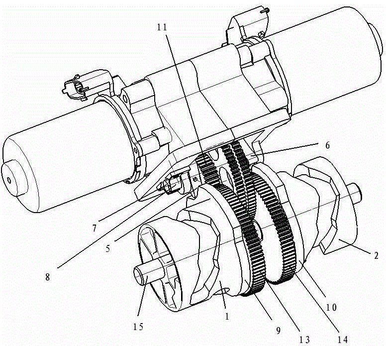
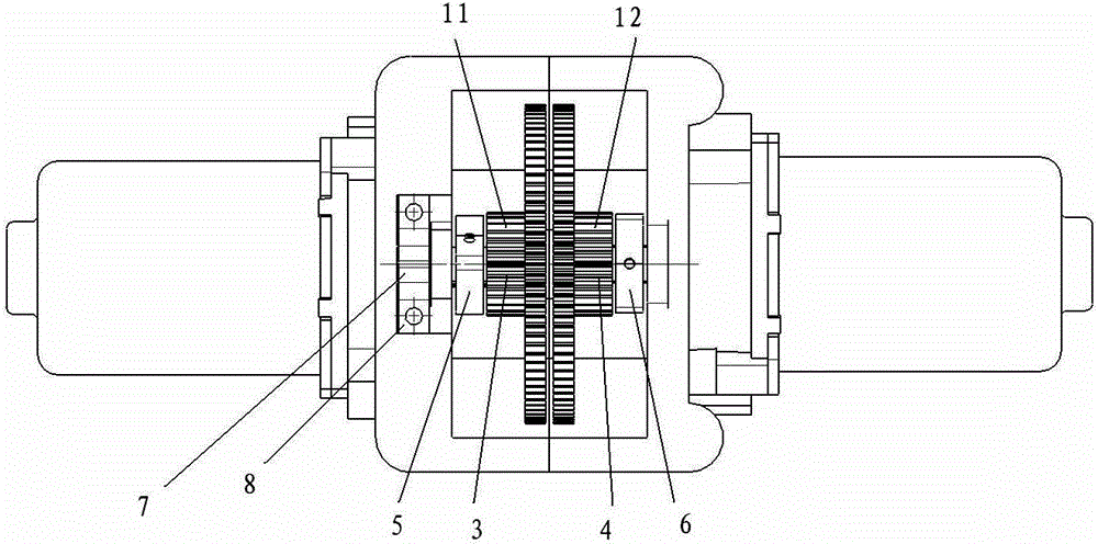
[0017] Such as figure 1 As shown, an automatic transmission shift drum interlock mechanism includes shift drums 1, 2, shift drum gears 13, 14, shift drum shaft 15 and interlock cams 9, 10, and also includes The interlocking camshaft 7 of the gear drum shaft 15 is connected with two main reduction gears 11, 12 on the interlocking camshaft 7, and the main reduction gears 11, 12 are respectively connected with the two gear shifting gears on the shifting drum shaft 15. The drum gears 13 and 14 mesh, and the two main reduction gears 11 and 12 are respectively driven by two independent motors, and the power is transmitted to the shift drum through gear transmission, and the two shift drums 1 and 2 drive four shift forks to generate Shift movement.

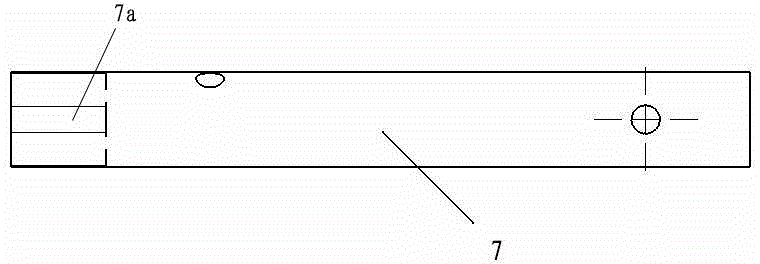
[0018] Such as figure 1 , figure 2 and Image 6 As shown, there are two arc-edge triangular cams 5 and 6 on the interlocking ...


PUM


Abstract

The invention provides a gear-shifting drum interlocking mechanism of an automatic gearbox. The gear-shifting drum interlocking mechanism comprises gear-shifting drums, gear-shifting drum gears, a gear-shifting drum shaft, interlocking cams and interlocking cam shafts which are parallel to each other and independent from the gear-shaft drum shaft, wherein two main reduction gears are connected to the interlocking cam shafts and are meshed with the two gear-shifting drum gears on the gear-shifting drum shaft respectively; and two arc-edge triangular cams are fixed on the interlocking cam shafts through pins, are positioned on the left side of one main reduction gear and the right side of the other main reduction gear respectively, are correspondingly matched with the interlocking cams on the gear-shifting drum shaft respectively, and are arranged by interlacing with a 60-degree angle. The gear-shifting drum interlocking mechanism has the beneficial effects that: the defect of error gear engagement or two-gear engagement or even multi-gear engagement caused by various interference factors of the gearbox is overcome, the response time of a system and the automobile driving safety are improved, and the gear-shifting drum interlocking mechanism is compact in structure and has a higher performance price ratio.

Description

technical field [0001] The invention belongs to the field of automobile transmissions, in particular to an interlock mechanism in shift control of a mechanical automatic transmission and a double-clutch automatic transmission. Background technique [0002] During the driving process of the car, due to the vibration of the car, the wear of the shift control mechanism, the change of working conditions and other interference factors, if there is no interlock device, the transmission is prone to mistaken gears or double gears or even multiple gears. , and because the speed of each gear of the transmission is different, it is easy to interfere, resulting in toothing or even serious damage to the transmission. At the same time, since the automatic transmission is more complicated than the manual transmission, TCU and motor are used instead of manual shifting, the cumulative error of the motor rotation angle, the limited resolution of the sensor and the temperature drift increase t...

Claims


Application Information

Patent Timeline
Patent Type & Authority Patents(China)
IPC IPC(8): F16H63/34
CPCF16H63/18F16H63/36
Inventor 邸永峰王海兵严皓钟振远田小桥
Owner 中国长安汽车集团有限公司
Why Eureka
Try Eureka