
Afteredge cutting mechanism of automotive interior ceiling
A technology of automotive interior parts and cutting mechanism, which is applied in metal processing and other directions, can solve the problems of long time and high cost of robot water jet cutting, and achieve the effect of reducing production cost, simple structure and high degree of automation
- Summary
- Abstract
- Description
- Claims
- Application Information
AI Technical Summary
Problems solved by technology
Method used
Image

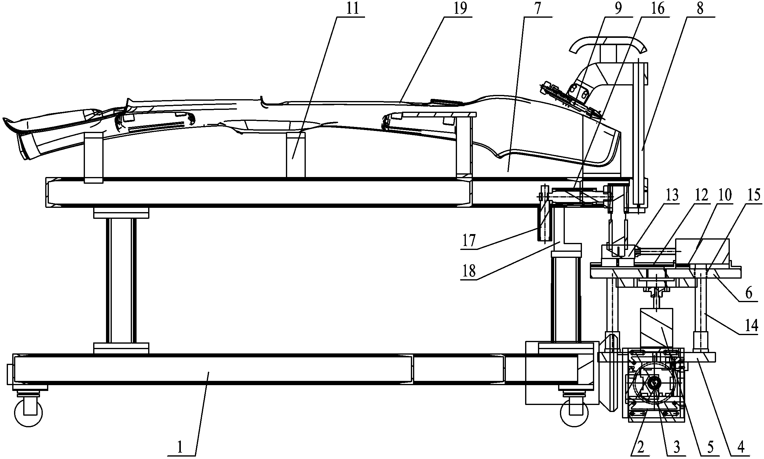
Examples
Embodiment Construction
[0009] The present invention will be further described below in conjunction with specific drawings and embodiments.
[0010] As shown in the figure: the roof rear edge cutting mechanism for automotive interior parts, the roof positioning mold rod 11 and the roof rear edge positioning tire mold 7 are fixed on the frame 1, and the servo motor and speed reducer are arranged on the side of the frame 1 Machine 2, the output shaft of the servo motor is connected with the input shaft of the reducer 2, and a transmission screw 3 is fixed on the output shaft of the reducer 2, and a drive screw nut is screwed on the drive screw 3, and on the drive screw nut A lifting mechanism mounting base 4 is fixed, a lifting drive cylinder 5 is fixed on the lifting mechanism mounting base 4, a left and right translation mechanism mounting base 6 is arranged above the lifting mechanism mounting base 4, the piston rod end of the lifting driving cylinder 5 is connected to the The left and right transla...
PUM
 Abstract
Description
Claims
Application Information