Lighting device and related projection system

A light-emitting device and a light-emitting light source technology, which is applied in the direction of lighting devices, projection devices, lighting device components, etc., can solve the problems of large light-emitting area and insufficient brightness, and achieve the effect of high brightness and small optical expansion

Active Publication Date: 2015-10-07
APPOTRONICS CORP LTD
View PDF1 Cites 0 Cited by
  • Summary
  • Abstract
  • Description
  • Claims
  • Application Information

AI Technical Summary

Problems solved by technology

[0004] However, in figure 1 In the light-emitting device shown, the problem of insufficient brightness caused by a large light-emitting area is often encountered

Method used


Image

  • Lighting device and related projection system
  • Lighting device and related projection system
  • Lighting device and related projection system

Examples


Embodiment 1

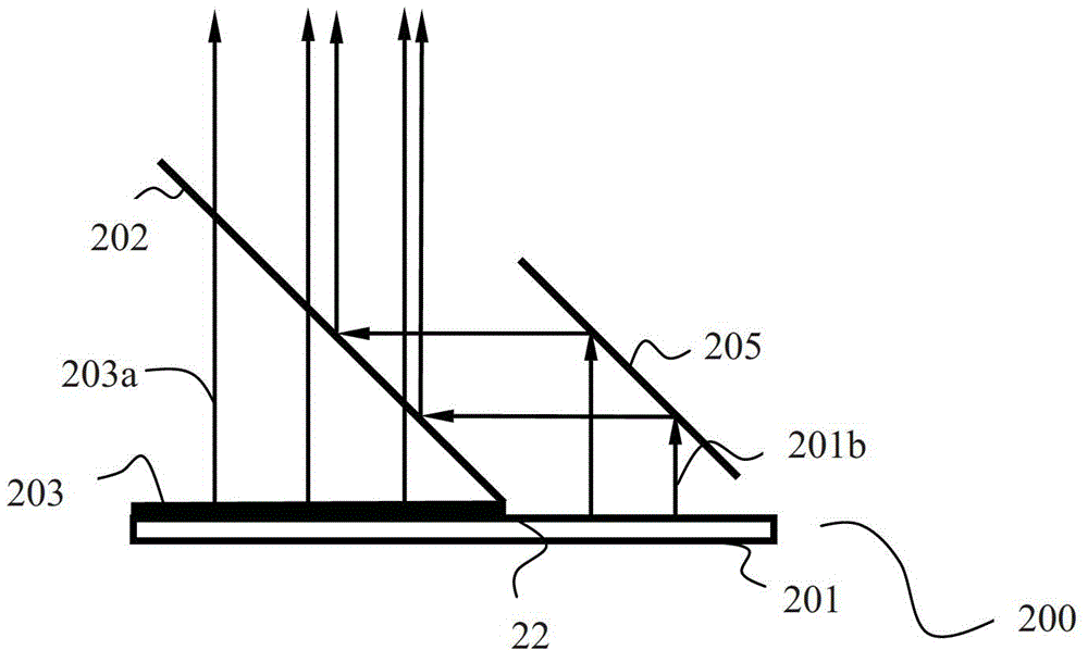
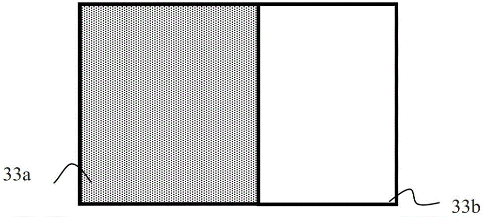
[0022] see figure 2 , figure 2 It is a structural schematic diagram of the light emitting device in this embodiment. In the light emitting device 200 of this embodiment, the light emitting source 201 includes a light emitting surface 22 having a first area and a second area, and is used for generating first light. Such as image 3 as shown, image 3 yes figure 2 The front view of the light emitting surface 22 in the light emitting device 200 shown. The light emitting surface 22 includes a first region 33a and a second region 33b. Since the areas of the first region and the second region are smaller than the area of ​​the entire light-emitting surface 22, and the first light emitted by the first region (not shown in the figure), the first light 201b emitted by the second region and the light generated by the light emitting element 201 Therefore, the etendue of the first light emitted from the first region and the first light 201b emitted from the second region are both...

Embodiment 2

[0038] see Figure 9 , Figure 9 It is another structural schematic diagram of the light emitting device in this embodiment. Different from the above embodiments, the wavelength conversion layer is independent of the luminous light source, and is arranged on the wavelength conversion device 909, and the wavelength conversion device 909 is driven to move by the driving device 911, so that the light spot formed by the first light on the wavelength conversion layer is as predetermined Paths act on the wavelength conversion layer. In this embodiment, the wavelength conversion layer is independent from the light source and is easier to dissipate heat, so as to avoid the problem of low conversion efficiency caused by its high temperature.

[0039] Specifically, for example, the light-emitting element 901 generates a beam of blue light, and part of the light 901b of the beam of blue light is reflected by the reflector 903, which is the first light 901b emitted from the second area;...


PUM


Abstract

The embodiment of the invention discloses a light-emitting device and a projection system. The light-emitting device comprises a light-emitting light source, a wavelength conversion layer and a light combining component, wherein the light-emitting light source comprises a light-emitting surface with a first area and a second area and is used for emitting first light; the wavelength conversion layer comprises a wavelength conversion material and is used for absorbing the first light emitted by the first area of the light-emitting light source to emit excited light; and the light combining component is used for receiving the first light emitted by the second area of the light-emitting light source and the excited light emitted by the wavelength conversion layer and combining the received first light and excited light into combined light in a mode that one light beam covers the other light beam. The brightness of the light-emitting device can be improved.

Description

technical field [0001] The invention relates to the technical field of illumination and display, in particular to a light emitting device and a related projection system. Background technique [0002] At present, the demand for white light in the lighting and display industry is increasing, and the requirements for brightness, service life and color of white light are getting higher and higher. [0003] Such as figure 1 as shown, figure 1 It is a structural diagram of a light-emitting device that generates white light used in the prior art. In the light emitting device 100, the light emitting element 101 is a blue LED chip for generating blue light. The light-emitting surface of the LED chip 101 is coated with yellow fluorescent powder 103 for absorbing blue light and generating yellow stimulated light. This yellow light is then combined with unabsorbed blue light to form white light. [0004] However, in figure 1 In the light-emitting device shown, the problem of insu...

Claims


Application Information

Patent Timeline
Patent Type & Authority Patents(China)
IPC IPC(8): G03B21/20G03B21/14F21V9/10G02B27/10F21V9/40
Inventor 杨佳翼李屹
Owner APPOTRONICS CORP LTD
Why Eureka
Try Eureka