a display system

A technology of display systems and light modulators, applied in instruments, projection devices, optics, etc., can solve the problems of poor feasibility and low light utilization rate, and achieve the improvement of light recovery efficiency, brightness and contrast, and light utilization rate. Effect

Active Publication Date: 2019-10-25
APPOTRONICS CORP LTD
View PDF7 Cites 0 Cited by
  • Summary
  • Abstract
  • Description
  • Claims
  • Application Information

AI Technical Summary

Problems solved by technology

[0005] Aiming at the defects of low light utilization rate and poor feasibility of the above-mentioned light recovery and reuse technology in the prior art, the present invention provides a display system with high light utilization rate and practical light recovery and reuse, including: a light source for emitting The first light; the uniform light device, including a light incident surface, used to receive the first light and make it uniform; the light modulator, used to receive at least part of the light emitted by the uniform light device and according to the image signal for incident on At least part of the light of the light modulator is modulated, and emits modulated light and non-modulated light; a light guiding device is used to guide at least part of the non-modulated light emitted by the light modulator to the light incident surface of the light uniform device, so that it passes through Enter the light modulator after uniform light device

Method used


Image

  • a display system
  • a display system
  • a display system

Examples


Embodiment 1

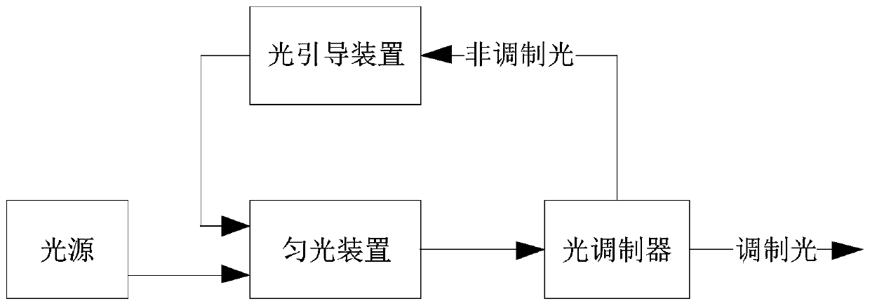
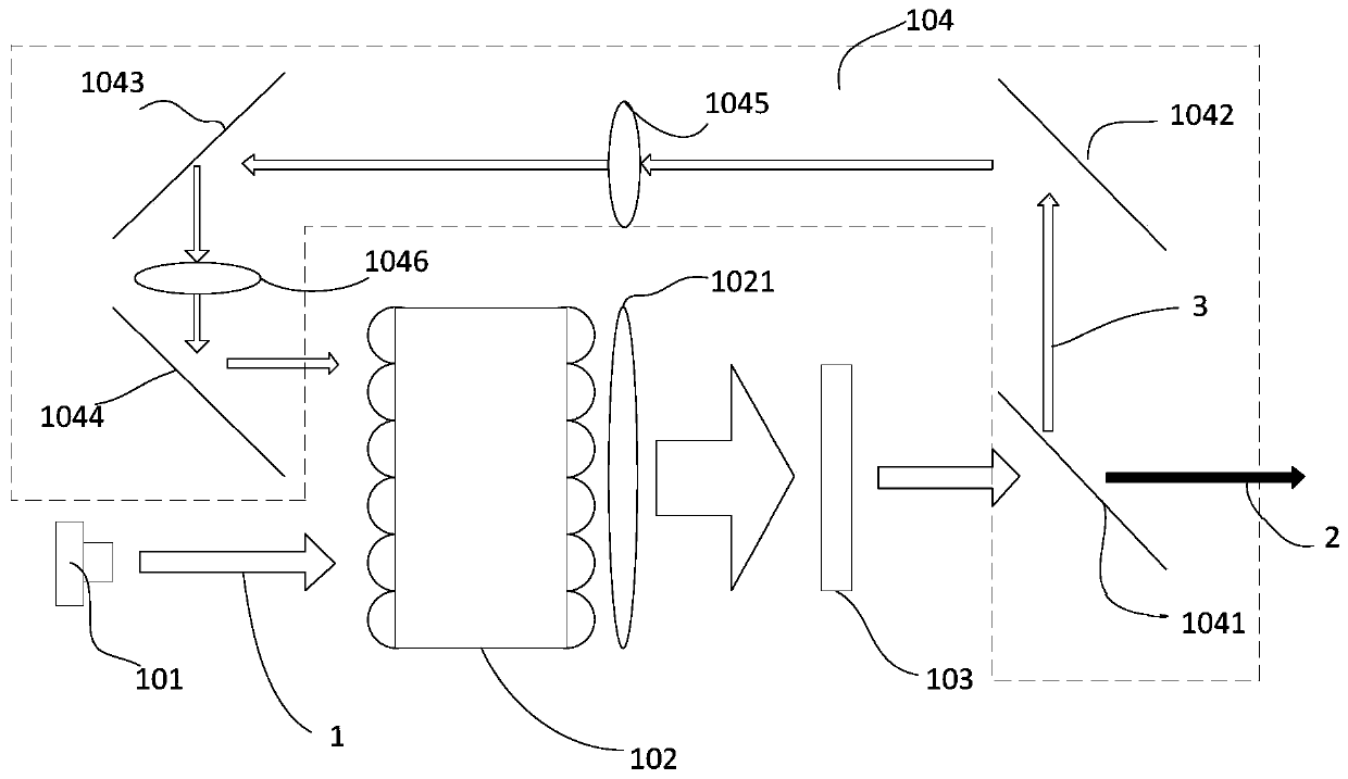
[0047] See Figure 3a , Figure 3a It is a schematic structural diagram of a display system according to Embodiment 1 of the present invention. The display system includes a light source 101 , a dodging device 102 , a light modulator 103 and a light guiding device 104 .

[0048] Wherein, the light source 101 is used to emit the first light 1 , and the homogenization device 102 includes a light incident surface, which is used to receive and homogenize the first light 1 . The light modulator 103 is used for receiving at least part of the light emitted by the dodging device 102 and modulating at least part of the light incident on the light modulator 103 according to the image signal, and emitting modulated light 2 and non-modulated light 3 . The light guiding device 104 is used to guide at least part of the non-modulated light 3 emitted by the light modulator 103 to the light incident surface of the light homogenizing device 102 , so that it enters the light modulator 103 agai...

Embodiment 2

[0072] See Figure 3b , Figure 3b It is a schematic structural diagram of the display system of Embodiment 2 of the present invention. The display system comprises a light source 101, a dodging device 102', a light modulator 103 and a light guiding device 104'. and Figure 3a The difference of the shown first embodiment is that the dodging device 102' in this embodiment is replaced by an integrating rod by a pair of fly-eye lenses.

[0073] In this embodiment, the light modulator 103 is a transmissive liquid crystal light valve, and for a specific description, refer to the description of in the first embodiment above.

[0074] In this embodiment, the light source 101 refers to the description about in the first embodiment.

[0075] In this embodiment, the light guiding device 104' also includes a mirror group composed of multiple mirrors and a lens group composed of multiple relay lenses. The difference is that the light guided by the light guiding device 104' is incid...

Embodiment 3

[0079] See Figure 3c , Figure 3c It is a structural schematic diagram of the display system of Embodiment 3 of the present invention. This embodiment and Figure 3a The difference of the first embodiment mainly lies in the difference in the way of combining the first light and the non-modulated light.

[0080] The display system of this embodiment includes a light source 101, a dodging device 102, a light modulator 103 and a light guiding device 104". The light source 101 is used to emit the first light 1, and the dodging device 102 includes a light incident surface for receiving the first light 1 and make it uniform. The light modulator 103 is used to receive at least part of the light emitted by the light homogenizing device 102 and modulate the light incident on the light modulator 103 according to the image signal, and emit modulated light 2 and non-modulated light 3 . The light guiding device 104 ″ is used to guide at least part of the non-modulated light 3 emitted b...


PUM


Abstract

A display system, comprising: a light source (101) used for emitting first light (1); a light homogenizing device (102) comprising a light-incident surface, and used for receiving and homogenizing the first light (1); a light modulator (103) used for receiving at least part of the light emitted by the light homogenizing device (102), modulating the at least part of the light incident on the light modulator (103) according to an image signal, and emitting modulated light (2) and non-modulated light (3); and a light guiding device (104) used for guiding at least part of the non-modulated light (3) emitted by the light modulator (103) to the light-incident surface of the light homogenizing device (102), so that the light passes through the light homogenizing device (102) and then enters the light modulator (103).

Description

technical field [0001] The invention relates to the field of display, in particular to a display system for non-modulated light that can recycle and reuse a light modulator. Background technique [0002] With the continuous promotion of digital teaching and the rapid development of the cinema industry, the importance of projectors has become more and more obvious, and the brightness of projectors, as an important parameter in the field of projection display, has become the focus of researchers in the industry. [0003] A basic projection system includes a light source, a light modulation device and a projection lens. After the light emitted by the light source is modulated by the light modulation device, it is projected onto the screen by the projection lens to display an image. Wherein, part of the light incident on the light modulation device is modulated and then enters the projection lens, while the rest of the non-modulated light is absorbed or converted into heat. The...

Claims


Application Information

Patent Timeline
Patent Type & Authority Patents(China)
IPC IPC(8): G03B21/14G02B27/28
CPCG02B27/283G03B21/14G02B27/10G02B27/18
Inventor 胡飞郭祖强米麟李屹
Owner APPOTRONICS CORP LTD
Why Eureka
Try Eureka