Vacuum Heat Insulator

a vacuum heat insulation and core member technology, applied in the field of vacuum heat insulation, can solve the problems of common use core members of vacuum heat insulation described above, disadvantages in the handleability and workability of glass fiber itself, and insufficient heat resistance to fibrous materials such as glass fiber, etc., to achieve superior handleability and workability, reduce environmental load, and improve heat resistance.

Inactive Publication Date: 2008-04-24
SAMSUNG R&D INSTITUTE JAPAN CO LTD
View PDF4 Cites 40 Cited by
  • Summary
  • Abstract
  • Description
  • Claims
  • Application Information

AI Technical Summary

Benefits of technology

[0020] The vacuum heat insulators according to the first to third inventions comprises the core member constituted by polyester fiber, being low in environmental load, and being very superior in recycling efficiency after use. In addition, the vacuum heat insulators according to the first and third inventions show a heat-insulating properties higher than that of the vacuum heat insulators constituted by open-cell polyurethane foam for use in refrigeratand / or others over an extended period of time, and are superior in handleability and workability when compared to those of glass fiber.
[0021] In particular in the first invention, a thin core member having a post-evacuation thickness in a particular range shows distinctive improvement in curved-surface processability. The polyester fiber, particularly polyethylene terephthalate fiber, for the core member is flexible and thus, deforms smoothly in the heat insulator even after evacuation. Such a vacuum heat insulator has a relatively small restoring force even when deformed, and there are smaller and fewer creases. For that reason, the vacuum heat insulator allows easier wrapping around cylindrical tanks in water supply equipment and cylindrical pipes in piping facility and also sufficiently tight adhesion thereto. The vacuum heat insulator also shows a heat-insulating properties greater than that of the vacuum heat insulator of an open-cell foam, and is superior in handleability in comparison to that of glass fiber.
[0022] In particular in the first invention, when a core member containing at least two kinds of polyester fibers different in melting point is used, it is possible to process it into sheet by a thermal-bonding method at relatively low temperature and thus to improve handleability and workability of core member, while suppressing generation of out-gas. In particular, its handleability and workability are significantly improved from those of conventional fibrous core materials, and become at levels almost equivalent to those of the polyurethane-foam plate-shaped core members.
[0023] The vacuum heat insulator according to the second invention, which includes a core member having a through-hole area and / or a notched area or multiple core members, can be used in various applications. The vacuum heat insulator also contains a polyester fiber core member higher in flexibility, and thus, causes fewer fracture of the external packaging member in the internal peripheral area of the through-hole area and / or notched area or in the external periphery of the core members when multiple core members are placed in the external packaging member during evacuation, and is superior in adhesiveness between the external packaging member and the core member.
[0024] In the vacuum heat insulator according to the third invention, in which the core member is contained in the external packaging member with the core member enclosed in an internal packaging member, the external packaging member is less vulnerable to scratches, and the core member is less likely to adhere to the opening of the external packaging member, which leads to improvement in yield of the vacuum heat insulatand / or thus in productivity.

Problems solved by technology

However, the commonly-used core members for vacuum heat insulator described above still have the following problems.
Core members of open-cell polyurethane foam are very superior in workability, handleability, lightness in weight, and others, but inferior in heat resistance to fibrous materials such as glass fiber.
Core members of glass fiber aggregate are very superior in heat-insulating properties without generation of out-gas (gases vaporizing form core member), but have a disadvantage in the handleability and workability of the glass fiber itself.
Although there are efforts to improve handleability, for example to improve operation of inserting a core member into the external packaging member, by needle-punching a sheet of glass fiber, it was not possible to overcome the difficulties in handling and workability derived from the material itself.
In particular, there still remain problems in working environment and handling, when the core member is recycled.
For example, seal opening of the external packaging member during recycling results in scattering of the glass fiber aggregate core member, causing problems in handleability and workability and also in environmental load.
Core members in combination of a glass fiber aggregate and other thermoplastic fiber are improved in handling to some extent but not sufficiently.
However, the core member still has problems of the deterioration in workability due to the glass wool itself and the deterioration in heat-insulating properties with time due to out-gas generated from the polypropylene resin fiber.
In addition, combined use of organic and inorganic fibers makes fractionation after use very difficult and thus, results in very poor recycling efficiency.
Although there are some reports on composites with rock wool, pulp, or the like, similarly to the composite with a thermoplastic fiber, use of a glass fiber inevitably causes the problems of the poor handleability and workability and high environmental load inherent to the glass fiber.
Although a vacuum heat insulator made only of an organic fiber, for example of a thermoplastic fiber, may possibly be used as a core member, there is no such commercially available heat insulator because of the problem of out-gas from the organic fiber.
Use of a 0.75-d polyester fiber floc as a core member was studied (Patent Document 5), but use of the fiber floc resulted in deterioration in handleability, and thus, prohibits production of practical products.
It is possible to process the fiber floc into sheet for improvement in handleability, but as described above, it is difficult to use a needle-punching method when an ultra-thin fiber is used, and use of a chemical bonding method leads to generation of out-gas, causing problems of larger change and drastic deterioration in heat-insulating properties with time.
However, it was difficult to bend a conventional thick core member having a vacuum thickness of 10 mm or more after evacuation.
Even if it was possible to deform a core member easily before evacuation, it was difficult to produce a vacuum heat insulator by using the deformed core member.
However, when a glass fiber having an average fiber length of 1 mm or less was used as a core member, reduction in thickness resulted in insufficient curved-surface processability.
Even if the vacuum heat insulator obtained may be easily deformed, the vacuum heat insulator could not be used easily for wrapping and lead to insufficient adhesion if used, because it tends to go back to its original flat plate shape and leave relatively large cockles generated when it is bent.
However, if a hard core member such as open-cell resin foam or inorganic powder is used, when the external covering material (external packaging member) in the internal peripheral area of the through-hole area or the notched area is evacuated or the cover material is sealed, a large load is applied to the internal peripheral area and causes fracture of the covering material and significant separation of the covering material from the core member, although such a phenomenon depends on the flexibility or the kind of the covering material used.
A similar problem arises when multiple core members are placed in an external packaging member and the rear faces of the external packaging member are sealed to each other along the periphery of the external packaging member and the external periphery of the core members.
Problems often arise in the regions particularly between multiple core members in the evacuation step.
It may be possible to smoothen the surface of the core member and thus to raise the adhesiveness between the covering material and the core member, but it demands an additional chamfering of the core member, which leads to decrease in productivity.
It is even difficult to smoothen the surface of the core member, especially if it is an inorganic material.
Each of the vacuum heat insulators above is prepared by placing a core member directly in an external packaging member, making the external packaging member evacuated inside, and sealing the opening of the external packaging member, but the method raised a problem in productivity of the vacuum heat insulator.
Specifically, when a core member is placed directly in an external packaging member, the external packaging member often suffers scratches, resulting in decrease in the yield of vacuum heat insulator.
Also when a core member is placed directly in an external packaging member, the core member easily adheres to the finally-sealed opening in the external packaging member, for example electrostatically, tightly to the extent that the deposited core member cannot be removed sufficiently, and thus, sealing of the opening results in formation of an air vent derived from the deposited core member interconnecting inside and outside of the external packaging member and thus in decrease in the yield of vacuum heat insulator.
Such a problem of decrease in yield was particularly distinctive, when a difficult-to-handle fiber floc was used as a core member.
In addition, when a core member of fiber floc is placed directly in an external packaging member, the filling operation is restricted for prevention of the scratches on the external packaging member as described above, and thus, it was difficult to fill the core member to a uniform thickness, which lead to decrease in heat-insulating properties.

Method used


Image

  • Vacuum Heat Insulator
  • Vacuum Heat Insulator
  • Vacuum Heat Insulator

Examples


examples a

Fiber for Use as Core Member

[0152] The polyester fibers shown in Table 1 were used. The polyester fibers were polyethylene terephthalate fibers having a fiber length of 51 mm.

example a1

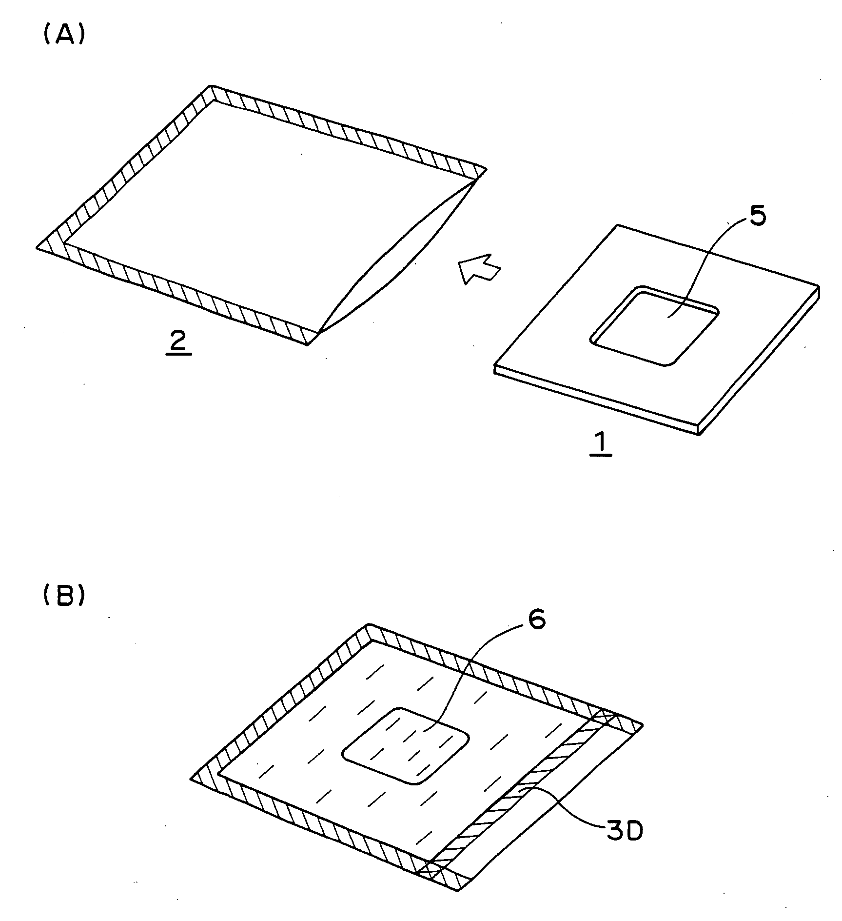
[0153] The polyester fiber shown in Table 1 was processed into sheet by a needle-punching method. The weight per unit area of the sheet immediately after processing was 550 g / m2. The sheet was cut into pieces of 200 mm×200 mm in size and dried at the temperature of 120° C. for 1 hour. After drying, four sheets were laminated, and the laminate was placed as a core member in an external packaging member of a gas barrier film having a four-layer structure of nylon, aluminum-deposited PET, aluminum foil, and high-density polyethylene, together with a gas-adsorbing member (COMBO, manufactured by Saes Getters Japan Co., Ltd). Then, the external packaging member was sealed by thermal fusion in a vacuum apparatus evacuated to an internal pressure of 0.01 Torr. The vacuum heat insulator obtained was 200 mm×200 mm in size and 10 mm in thickness. The density of the core member in the vacuum heat insulator obtained was 220 kg / m3.

[0154]

[0155] Vacuum heat insulators were prepared by a method sim...

examples b

Preparation of Gas-Adsorbing Member

Gas-Adsorbing Member A

[0164] Two sheets of PET nonwoven fabric having a weight per unit area of 50 g / m2 (dimension: 50 mm×100 mm) of a polyethylene terephthalate fiber having an average fiber size of 1.5 denier and an average fiber length of 51 mm were layered and sealed in three directions. Ten g of a gas-adsorbing substance was placed therein, and the opening was sealed, to give a gas-adsorbing member A.

[0165] Gas-Adsorbing Member B

[0166] A gas-adsorbing member B was prepared by a method similar to that for the gas-adsorbing member A, except that a PET nonwoven fabric having a weight per unit area of 60 g / m2 was used.

[0167] Gas-Adsorbing Member C

[0168] A gas-adsorbing member C was prepared by a method similar to that for the gas-adsorbing member A, except that a PET nonwoven fabric having a weight per unit area of 150 g / m2 was used.

[0169] Gas-Adsorbing Member D

[0170] Two sheets of a PP nonwoven fabric having a weight per unit area of 60 ...


PUM

PropertyMeasurementUnit
diameteraaaaaaaaaa
thicknessaaaaaaaaaa
melting pointaaaaaaaaaa

Abstract

The present invention provides a heat insulator that is extremely low in environmental load during production and recycling, is superior in handleability and workability, and shows favorable heat-insulating properties over an extended period of time. The present invention relates to vacuum heat insulator, comprising at least a core member and an external packaging member that stores the core member and can keep inside under reduced pressure, wherein the core member is a sheet-shaped fiber aggregate containing a polyester fiber having fiber size of 1 to 6 deniers in an amount of 50 wt % or more.

Description

TECHNICAL FIELD [0001] The present invention relates to a vacuum heat insulator for use as a heat insulator for refrigerator, vending machine, cooling box, refrigerator truck, hot water tank, ice tank, vacuum insulating piping, molded head lining of automobiles, bath tub, and others. BACKGROUND ART [0002] Various heat insulators different in structure and characteristic have been used for insulation of refrigerator, vending machine, cooling box, refrigerator truck, hot water tank, ice tank, vacuum insulating piping, molded head lining of automobiles, bath tub, and others. Recently, many vacuum heat insulators showing superior heat-insulating properties have been used in these applications. Such a vacuum heat insulator generally has a structure prepared by placing a core member in a gas-barrier external packaging member, for example, of a metal-deposited film and sealing it while making inside under reduced pressure. The heat-insulating properties, productivity, and handleability of ...

Claims


Application Information

Patent Timeline
Patent Type & Authority Applications(United States)
IPC IPC(8): B32B3/02
CPCF16L59/065F25D23/06F25D2201/14Y10T428/231Y10T428/1359Y10T428/13Y10T428/1303Y10T428/1369Y10T428/1362Y10T428/1352F16L59/06B32B5/02
Inventor TAKASHIMA, HIROYUKIYAMASHITA, KOUJI
Owner SAMSUNG R&D INSTITUTE JAPAN CO LTD
Why Eureka
Try Eureka