Wavelength conversion apparatus and luminous apparatus

A wavelength conversion device and wavelength conversion layer technology, applied in the optical field, can solve the problems of insufficient LED brightness, high cost of blue laser, and low service life, and achieve the effect of reducing etendue

Active Publication Date: 2014-12-10
APPOTRONICS CORP LTD
View PDF5 Cites 0 Cited by
  • Summary
  • Abstract
  • Description
  • Claims
  • Application Information

AI Technical Summary

Problems solved by technology

The problem of both is that the brightness of the LED is insufficient, which is mainly due to the large light-emitting area of ​​a single LED, which makes the optical expansion of the light beam emitted by the LED too large.
Of course, the latter can use blue light laser as the excitation light source, but the cost of blue light laser is higher, and the service life is much lower than that of LED

Method used


Image

  • Wavelength conversion apparatus and luminous apparatus
  • Wavelength conversion apparatus and luminous apparatus
  • Wavelength conversion apparatus and luminous apparatus

Examples


Embodiment Construction

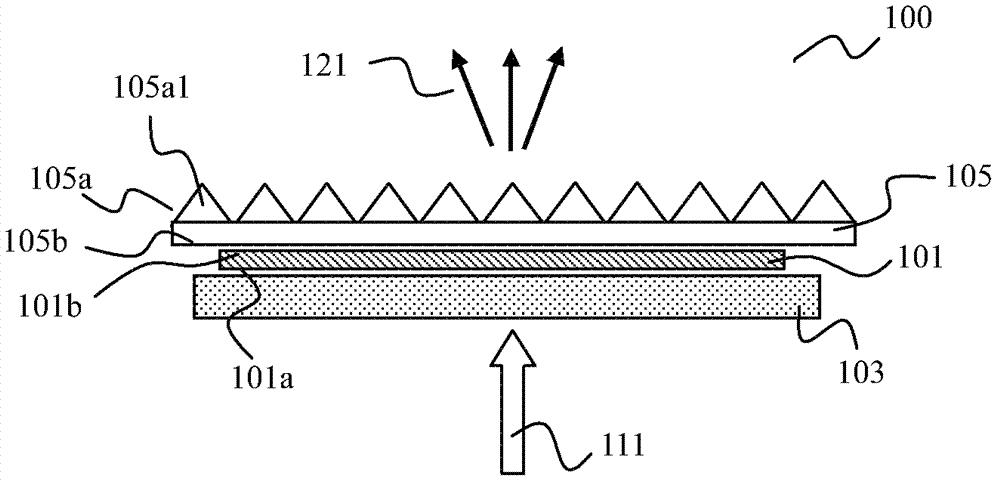
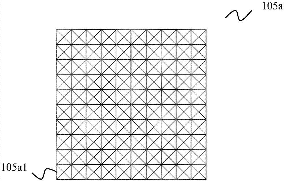
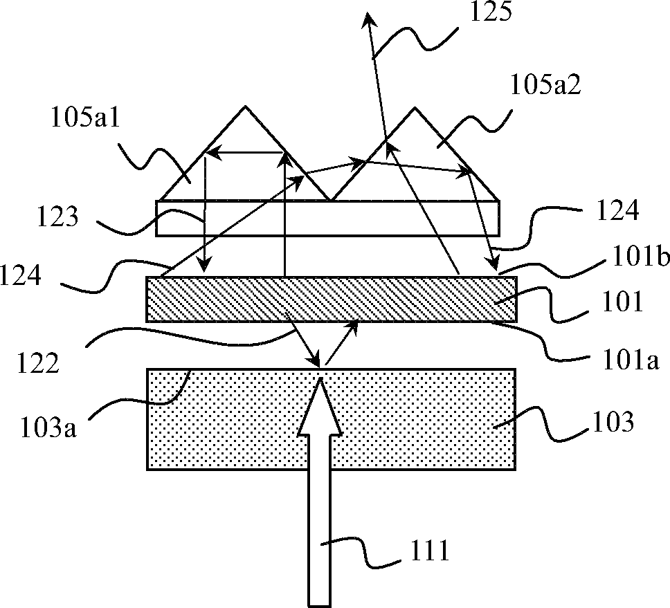
[0018] The structure of the first embodiment of the present invention is as Figure 1a shown. The wavelength conversion device 100 includes a wavelength conversion layer 101 for absorbing the excitation light 111 and emitting the received light 121. The wavelength conversion layer 101 includes opposite first surfaces 101a and second surfaces 101b; A reflective layer 103 on one side, the reflective layer 103 reflects the received light; it also includes a light distribution transformation layer 105 located on the second surface 101b side of the wavelength conversion layer, and the light distribution transformation layer 105 includes an opposite plane 105b and a microstructure surface 105a , the plane 105b faces the second surface 101b of the wavelength conversion layer, and the microstructure surface 105a includes a plurality of microstructure units 105a1.

[0019] The light distribution conversion layer is made of transparent materials, such as glass or transparent organic mat...


PUM


Abstract

The invention provides a wavelength conversion apparatus. The wavelength conversion apparatus comprises a wavelength conversion layer, a reflecting layer and a light distribution transformation layer, wherein the wavelength conversion layer comprises a first surface and second surface which are opposite to each other; the reflecting layer is located on one side of the first surface of the wavelength conversion layer and reflects stimulated light; the light distribution transformation layer is located on one side of the second surface of the wavelength conversion layer. The light distribution transformation layer comprises a plane and a microstructure surface which are opposite to each other. The plane faces the second surface of the wavelength conversion layer. The microstructure surface comprises a plurality of microstructure units. The shape of the microstructure unit is a pyramid or a cone. The invention also provides a luminous apparatus which comprises the wavelength conversion apparatus and an excitation light source emitting the excitation light. In the wavelength conversion apparatus and the luminous apparatus of the invention, the light distribution transformation layer is used to reflect the small-angle light, and propagation and scattering of the light between the light distribution transformation layer and the reflecting layer are used to realize compression of the angel the light emitted by the wavelength conversion layer so as to reduce an optical extended amount of luminescence.

Description

technical field [0001] The invention relates to the field of optics, in particular to a wavelength conversion device and a light emitting device. Background technique [0002] At present, semiconductor light sources have been paid more and more attention by people. Especially in the field of projection display, since the service life of traditional light bulbs is only 3000 hours, the demand for long-life light sources is very urgent. [0003] There are two current solutions. The first is to directly use a light emitting diode (LED, light emitting diode) as a monochromatic light source, and the other is to use a blue LED to excite a wavelength conversion device to generate various colors of light as disclosed in US Patent No. 7,547,114. The problem of both is that the brightness of the LED is insufficient, which is mainly due to the large light-emitting area of ​​a single LED, which makes the etendue of the light beam emitted by the LED too large. Of course, the latter can...

Claims


Application Information

Patent Timeline
Patent Type & Authority Patents(China)
IPC IPC(8): H01L33/50
Inventor 李屹
Owner APPOTRONICS CORP LTD
Why Eureka
Try Eureka