Mixed light source projection light engine system

A technology of mixing light sources and projection light, which is applied in optics, instruments, projection devices, etc., and can solve the problems that LEDs cannot meet the market demand for high brightness, energy utilization, and color purity reduction.

Pending Publication Date: 2017-09-01
SHENZHEN EVIEWTEK TECH CO LTD
View PDF5 Cites 0 Cited by
  • Summary
  • Abstract
  • Description
  • Claims
  • Application Information

AI Technical Summary

Problems solved by technology

Using blue LEDs to excite green phosphors to obtain green light has been commercialized. Although the brightness has been improved, there are also shortcomings: the spectral range is too wide. Although the main wavelength is in the green light range, there is still some energy in other wavelength ranges. The half-maximum width (FWHM) of phosphor-excited green LEDs has more than doubled to 100nm, while ordinary green LEDs are only 44nm; the color purity is greatly reduced, and the energy in other primary color ranges cannot be effectively utilized by the system; fluorescent The luminous angle of the powder-excited LED increases, which increases the etendue of the light source, which puts pressure on the design of the subsequent system
However, laser projection also has disadvantages that are difficult to overcome: true green lasers have not yet been commercialized, and the cost is too high. Most of the current green lasers are produced based on frequency doubling technology; there are security problems; The display image is disturbed and appears light and dark granular, which is prone to visual fatigue and greatly reduces sensory comfort
[0005] From this point of view, the projection system with LED as the light source can no longer meet the high-brightness market demand, and the various defects of the pure laser projection system cannot be commercialized.

Method used


Image

  • Mixed light source projection light engine system
  • Mixed light source projection light engine system
  • Mixed light source projection light engine system

Examples


Embodiment Construction

[0067] The following will clearly and completely describe the technical solutions in the embodiments of the present invention with reference to the accompanying drawings in the embodiments of the present invention. Obviously, the described embodiments are only some, not all, embodiments of the present invention. Based on the embodiments of the present invention, all other embodiments obtained by persons of ordinary skill in the art without making creative efforts belong to the protection scope of the present invention.

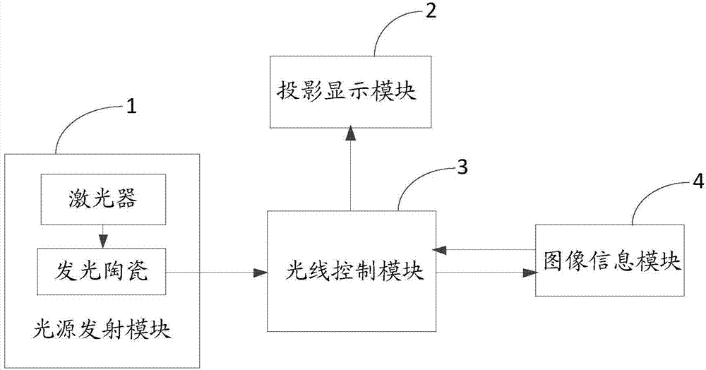
[0068] The invention provides a mixed light source projection light engine system, such as figure 1 As shown, it includes: a light source emitting module 1, a light control module 2, an image information module 3, and a projection display module 4; wherein, the light source emitting module 1 includes at least a laser for emitting a laser beam, and a laser set on the transmission optical path of the laser beam Luminous ceramics; the laser beam and the luminous ...


PUM


Abstract

The invention discloses a mixed light source projection light engine system, which comprises a light source emitting module, a light ray control module, an image information module and a projection display module, wherein the light source emitting module at least comprises a laser used for emitting laser beams and a luminous ceramic arranged on the transmission optical path of the laser beam; the laser beam and the luminous ceramic have different colors; the light source emitting module provides a mixed light source through the laser and the luminous ceramic; the light source is transmitted to the light ray control module; the light ray control module processes the mixed light source transmitted by the light source emitting module; the mixed light source is transmitted to the image information module; light rays reflected back by the image information module are transmitted to the projection display module for projection display. Through the mutual effects of the four modules, the laser is used for being combined with the luminous ceramic to be used as a light source, so that the laser scattered spots can be sufficiently eliminated; the high optical flux can be obtained; the heat stability is high; the optical engine brightness is improved; the optical expansion quantity is reduced; the service life is prolonged; the system light energy utilization rate is improved.

Description

technical field [0001] The invention relates to the display field, in particular to a mixed light source projection light engine system. Background technique [0002] Micro projectors have strict requirements on brightness, resolution, volume, power consumption, cost and heat dissipation. In order to achieve high brightness, high resolution, small size, low power consumption and low cost micro projection system, it is necessary to make great improvements or even innovations in many aspects such as light sources, light modulation devices, optical systems and optical devices. [0003] Most of the current micro-projectors use LEDs as lighting sources. LED has the advantages of small size, long life, fast response, energy saving and environmental protection, etc., but in micro projection applications, there are still problems such as low LED luminous flux, and the luminous flux per unit etendue is lower than traditional projection light sources, and excessive heat generation, e...

Claims


Application Information

Patent Timeline
Patent Type & Authority Applications(China)
IPC IPC(8): G03B21/20
CPCG03B21/204G03B21/206G03B21/2066G03B21/208
Inventor 贺银波陆巍
Owner SHENZHEN EVIEWTEK TECH CO LTD
Why Eureka
Try Eureka