Adjustable coherence detector structure

A technology of detectors and balanced detectors, applied in electromagnetic receivers, modulated carrier systems, digital transmission systems, etc., can solve problems such as high process requirements, small manufacturing tolerances, and limited working bandwidth, so as to achieve mature manufacturing processes and The effect of large tolerance and reduced loss

Active Publication Date: 2013-01-30
WUHAN TELECOMM DEVICES
View PDF6 Cites 2 Cited by
  • Summary
  • Abstract
  • Description
  • Claims
  • Application Information

AI Technical Summary

Problems solved by technology

[0006] 1. The phase introduced by the butterfly waveguide can only be very accurate for a certain wavelength, and there will be deviations for other wavelengths, and the 90-degree optical hybrid itself is a broadband device, so the butterfly waveguide will limit its operating bandwidth
[0007] 2. The butterfly waveguide itself introduces a certain loss
[0008] 3. Butterfly waveguides have smaller manufacturing tolerances than multimode coherent couplers, and have very high process requirements, so they are not suitable for mass production

Method used


Image

  • Adjustable coherence detector structure
  • Adjustable coherence detector structure
  • Adjustable coherence detector structure

Examples


Embodiment Construction

[0030] In order to facilitate a further understanding of the structure and achieved effects of the present invention, preferred embodiments are described in detail below in conjunction with the accompanying drawings.

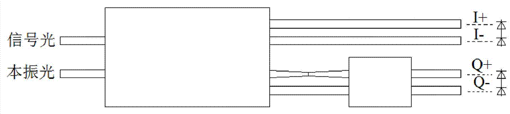
[0031] As shown in Figure 4, the adjustable coherent detector structure of the present invention includes two input waveguides 1, a 2×4 multimode coherent coupler 2, an adjustable electrode 3, a 2×2 multimode coherent coupler 4, Four output waveguides 5 and two pairs of balanced detectors 6 . The positional relationship of the above components is: the output terminal of the 2×4 multimode coherent coupler 2 is directly connected to the input terminal of the 2×2 multimode coherent coupler 4, and the adjustable electrode 3 is located in the 2×4 multimode coherent coupler 2 Above the connection with the 2×2 multimode coherent coupler 4; the two input waveguides 1 are connected to the input end of the 2×4 multimode coherent coupler 2, and are symmetrically distribute...


PUM


Abstract

The invention discloses an adjustable coherence detector structure. The adjustable coherence detector structure comprises two input waveguides connected with a 2*4 multimode coherence coupler, the 2*4 multimode coherence coupler used for demodulating two pairs of synchronizing signals, an adjustable electrode used for causing local refraction rate variation, a 2*2 multimode coherence coupler used for translating the synchronizing signals into orthogogonal signals, four output waveguides and two pairs of balance detectors, wherein the output end of the 2*4 multimode coherence coupler is directly connected with the input end of the 2*2 multimode coherence coupler, and the adjustable electrode is positioned above the joint of the two multimode coherence couplers; and the two output waveguides are connected with the output end of the 2*4 multimode coherence coupler, the other two output waveguides are connected with the output end of the 2*2 multimode coherence coupler, and the two pairs of balance detector are used for collimating the four output waveguides. The adjustable coherence detector structure provided by the invention can be used for realizing signal demodulation in an achiasmate manner, and is larger in tolerance and operation bandwidth.

Description

technical field [0001] The invention relates to an optoelectronic device for communication, in particular to an adjustable coherent detector structure which realizes signal demodulation without crossover and has larger tolerance and working bandwidth. Background technique [0002] In recent years, 100Gbit / s coherent optical fiber communication systems have been extensively studied. The integrated coherent receiver is one of the key components of high-speed coherent communication systems. It includes polarization beam splitters, 90-degree optical hybrids, balanced detectors and transimpedance Basic components such as amplifiers. Among these components, 90-degree optical hybrids can be divided into three categories: free space type, optical fiber type and waveguide type according to the realization form. Among them, the free-space type and the optical fiber type have commercial separation devices, but these separation devices are too large to be integrated with other compone...

Claims


Application Information

Patent Timeline
Patent Type & Authority Applications(China)
IPC IPC(8): H04B10/61H04L27/227
Inventor 刘卫华米全林余向红
Owner WUHAN TELECOMM DEVICES
Why Eureka
Try Eureka