Non-metal expansion joint for slag discharge pipeline of boiler

A slag discharge pipe and non-metallic technology, which is applied in expansion compensation devices for pipelines, pipe components, pipeline protection, etc., can solve the problem of difficulty in maintaining a uniform distribution of the temperature insulation layer, the decline of the temperature insulation effect, and the cavity of the temperature insulation layer, etc. problems, to achieve the effect of ensuring long-term effective operation and compact structure

Active Publication Date: 2014-07-02
AEROSUN CORP
View PDF7 Cites 1 Cited by
  • Summary
  • Abstract
  • Description
  • Claims
  • Application Information

AI Technical Summary

Problems solved by technology

However, after reciprocating compression, it is difficult for the temperature insulation layer to maintain the original uniform distribution state. When the compression recovers, the temperature insulation layer often appears "void" due to deviation from the original position, resulting in a decrease in the temperature insulation effect, or even failure.
[0003] Moreover, for such expansion joints with conventional structures, the axial compensation amount is generally limited to about one-third of the effective length of the ring belt (commonly known as the opening gear). In order to achieve a large compensation amount, the axial length needs to be increased

Method used


Image

  • Non-metal expansion joint for slag discharge pipeline of boiler
  • Non-metal expansion joint for slag discharge pipeline of boiler
  • Non-metal expansion joint for slag discharge pipeline of boiler

Examples


Embodiment 1

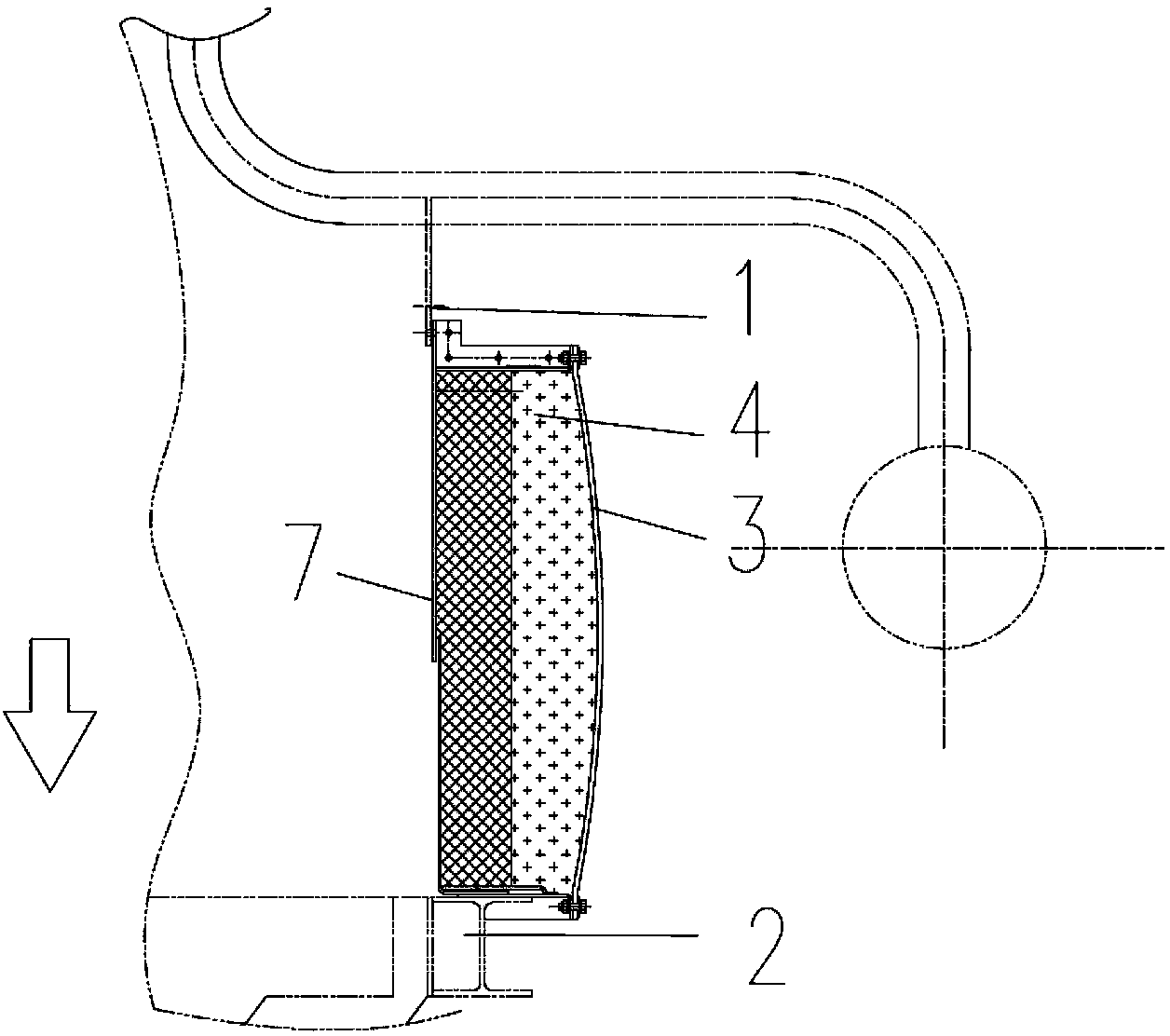
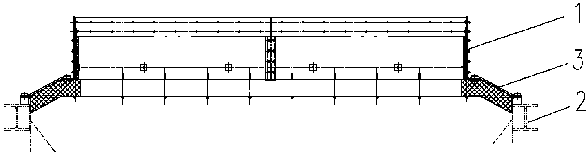
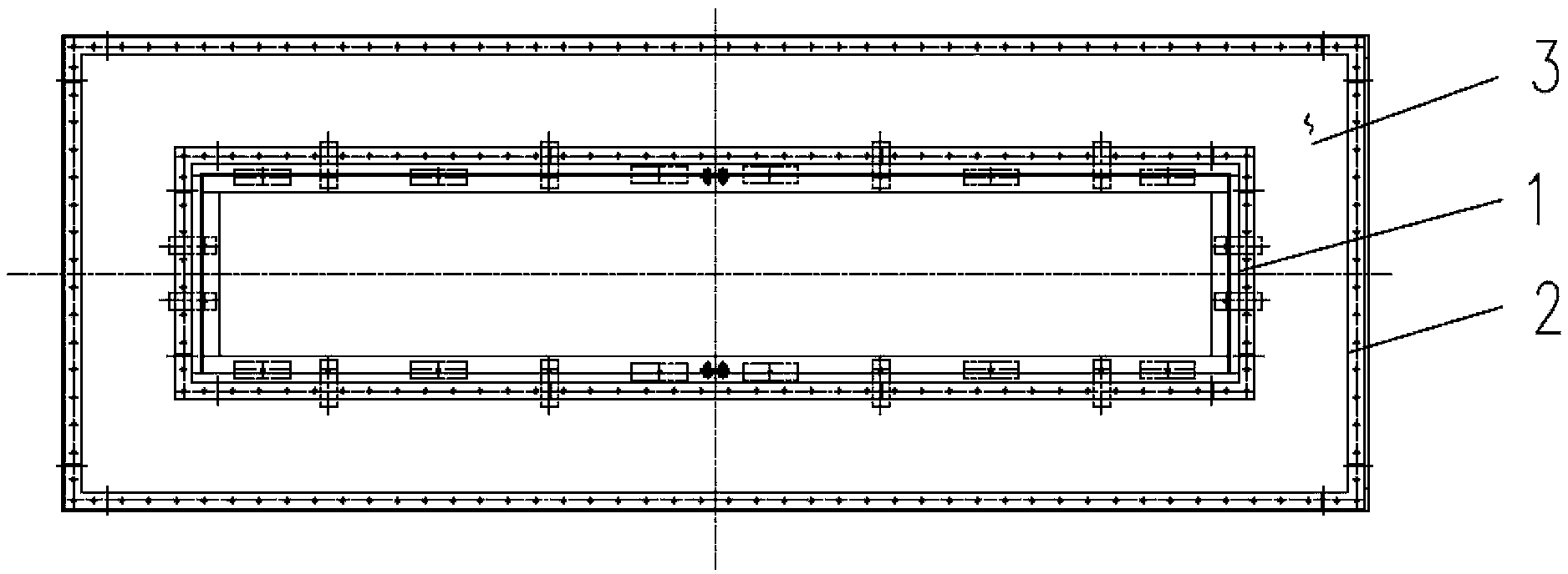
[0014] The non-metallic expansion joint of the boiler slag discharge pipeline in this embodiment is as attached figure 2 As shown, it includes a rectangular upper frame 1 and a lower frame 2 respectively connected to the upper pipeline and the lower pipeline; the flow section of the upper frame 1 is smaller than the flow section of the lower frame 2, and the two circles are equally spaced, and the distance between them is axial About 1.2 times of the displacement (1-1.5 times can make the inclination angle of the flexible ring belt less than 45 degrees when the axial position is located, and the effect is better). The 1st circle of the upper frame has a lower horizontal flange, the 2nd circle of the lower frame has an upper horizontal flange, and the upper horizontal flange and the lower horizontal flange are fixed "back" by the outer peripheral pressure plate 5 Zigzag flexible ring belt 3, the inner side of flexible ring belt 3 is fixed temperature-resistant fiber blanket (c...


PUM


Abstract

The invention relates to a non-metal high-temperature resistant expansion joint for a slag discharge pipeline of a boiler, belonging to the technical field of conveying pipelines. The non-metal expansion joint comprises an rectangular upper frame and a rectangular lower frame which are respectively connected to an upper pipeline and a lower pipeline; the flow area of the upper frame is smaller than that of the lower frame, the average spacing between the circumference of the upper frame and the circumference of the lower frame is 1-1.5 times that of the axial displacement, a lower horizontal turnup flange is arranged on the circumference of the upper frame, an upper horizontal turnup flange is arranged on the circumference of the lower frame, a concentric-shaped flexible ring strip is fixed between the upper horizontal turnup flange and the lower horizontal turnup flange, and a concentric-shaped heat insulation layer is fixed at the inner side of the flexible ring strip. The expansion joint structure which radially extends, disclosed by the invention, breaks through the traditional expansion joint which axially extends. The non-metal high-temperature resistant expansion joint disclosed by the invention effectively overcomes the defect that an internal heat insulation layer of the conventional non-metal expansion joint of the slag discharge pipe of the boiler is incapable of resetting due to large compression displacement and can effectively operate for a long time. In addition, the concentric-shaped structure can absorb larger axial displacement within a shorter axial length and is very compact in structure.

Description

technical field [0001] The invention relates to an expansion joint, in particular to a non-metallic expansion joint of a high-temperature-resistant boiler slag discharge pipeline, which belongs to the technical field of conveying pipelines. Background technique [0002] Expansion joints are commonly used components at pipeline connections. According to the applicant's understanding, the existing boiler slag discharge pipeline and the furnace bottom joint have high temperature, thermal expansion and contraction, and large axial displacement caused by boiler settlement. figure 1 Insulated expansion joint connection shown. The expansion joint of this kind of rectangular cross-section pipeline is composed of a flexible ring 3, an upper and lower inner liner 7, and a temperature insulation layer 4 clamped between the ring and the inner liner, and is connected to the upper and lower sides in an axial connection. between pipes. When absorbing axial displacement, the thermal insu...

Claims


Application Information

Patent Timeline
Patent Type & Authority Patents(China)
IPC IPC(8): F16L51/00F16L59/04F16L59/12
Inventor 洪建凡贾晓伟许松亚
Owner AEROSUN CORP
Why Eureka
Try Eureka