Large compensation external pressure expansion joint with heat preservation reset
An expansion joint and compensation technology, which is applied in the field of large compensation external pressure bellows expansion joints, can solve the problems of uneven deformation of bellows, poor stability, and large expansion joint compensation, so as to prevent vacancies and meet fatigue life , the effect of reducing the number of
- Summary
- Abstract
- Description
- Claims
- Application Information
AI Technical Summary
Problems solved by technology
Method used
Image
Examples
Embodiment 1
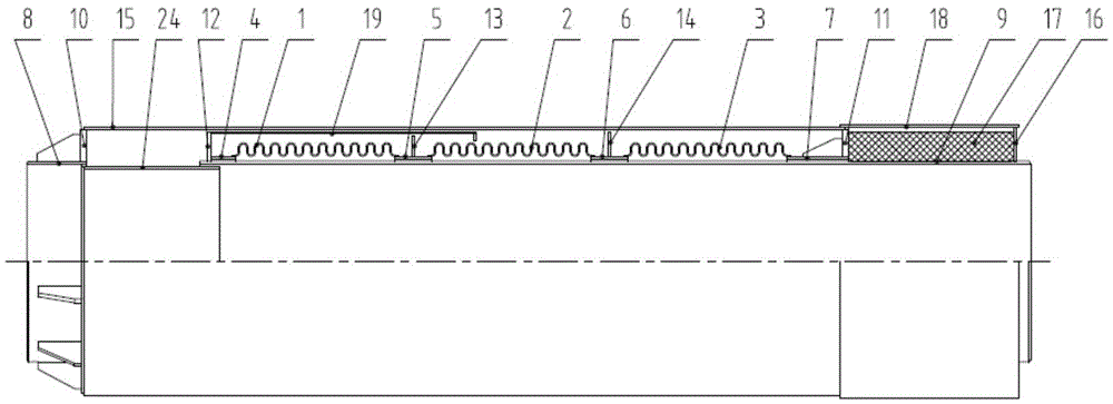
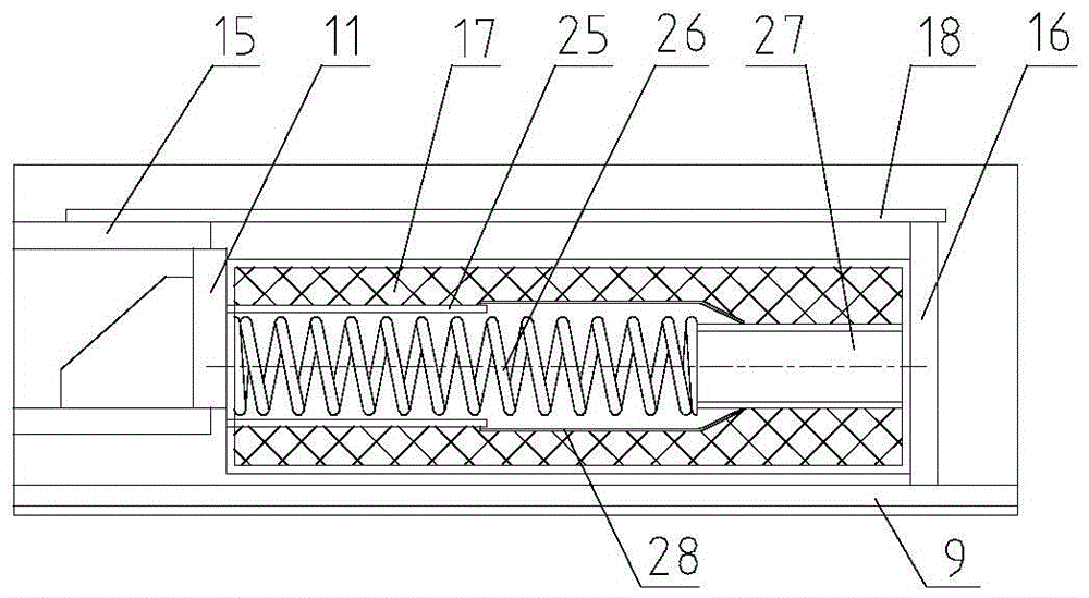
[0021] In this embodiment, the large compensation external pressure expansion joint with thermal insulation reset has a structure as follows figure 1 As shown, it includes an outer tube 15 and an inner tube 9 installed in the outer tube 15. One end of the inner tube 9 is covered with a guide tube 24, and the guide tube 24 is externally connected to the end tube 8. The right end of the end tube 8 is provided with a first pressure bearing ring plate 10, and the upper end of the first pressure bearing ring plate 10 is fixed on the left end of the outer tube 15, and the lower end is fixed on the outer wall of the end tube 8. A first axial displacement gap is provided between the first pressure bearing ring plate 10 and the inner pipe 9, and a guide tube 24 is arranged in the first axial displacement gap, so that the inner tube 9 passes through the guide tube 24 and the end pipe 8 are inserted into each other, so that the inner tube 9 can slide axially along the guide tube 24 . In...
Embodiment 2
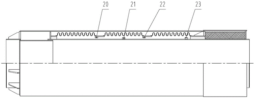
[0026] The difference between this embodiment and Embodiment 1 is that the equal displacement component is located between the inner tube 9 and the three-section corrugated pipe, and includes a set of left limit stoppers installed on the lower end surface of the short joint on the left side of the corrugated pipe And be installed on the inner pipe 9 and be positioned at one group of right limit stops below bellows. The displacement equalizing assembly of this embodiment has a structure such as figure 2 As shown, it includes a first left limit stop 20, a first right limit stop 21, a second left limit stop 22 and a second right limit stop 23, wherein the first left limit stop The position stopper 20 is fixed on the lower end surface of the second short connection pipe 5, the second left limit stopper 22 is fixed on the lower end surface of the third short connection pipe 6, the first right limit stopper 21 and the second right limit stopper The stop block 23 is fixed on the ou...
PUM
 Abstract
Description
Claims
Application Information
 - R&D
- Intellectual Property
- Life Sciences
- Materials
- Tech Scout
- Unparalleled Data Quality
- Higher Quality Content
- 60% Fewer Hallucinations
Browse by: Latest US Patents, China's latest patents, Technical Efficacy Thesaurus, Application Domain, Technology Topic, Popular Technical Reports.
© 2025 PatSnap. All rights reserved.Legal|Privacy policy|Modern Slavery Act Transparency Statement|Sitemap|About US| Contact US: help@patsnap.com


