An experimental device for launching an arrow-borne electric field rod on the ground

An experimental device and technology for extending rods, which can be used in projectiles, self-propelled bombs, offensive equipment, etc., and can solve problems such as damage to structures that cannot be extended.

Active Publication Date: 2014-10-08
NAT SPACE SCI CENT CAS
View PDF4 Cites 0 Cited by
  • Summary
  • Abstract
  • Description
  • Claims
  • Application Information

AI Technical Summary

Problems solved by technology

[0006] 3. The ground expansion test of the extension rod cannot damage the structure of the extension rod;

Method used


Image

  • An experimental device for launching an arrow-borne electric field rod on the ground
  • An experimental device for launching an arrow-borne electric field rod on the ground
  • An experimental device for launching an arrow-borne electric field rod on the ground

Examples


Embodiment Construction

[0044] The present invention will be further described below in conjunction with the accompanying drawings and embodiments.

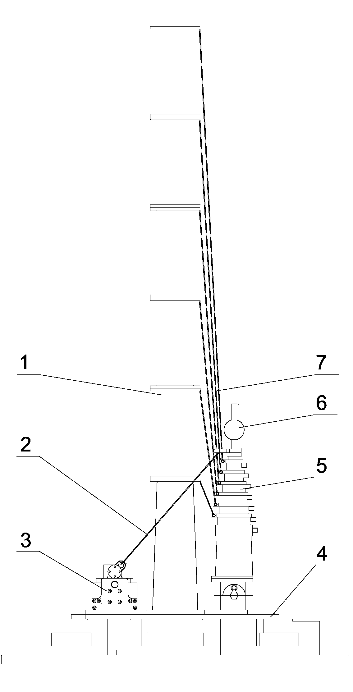
[0045] (1) The present invention simulates the clamping and releasing state of the electric field stretching rod under the specified rotational speed of the rocket, such as image 3 , Figure 4 , Figure 5 and Figure 6 shown.

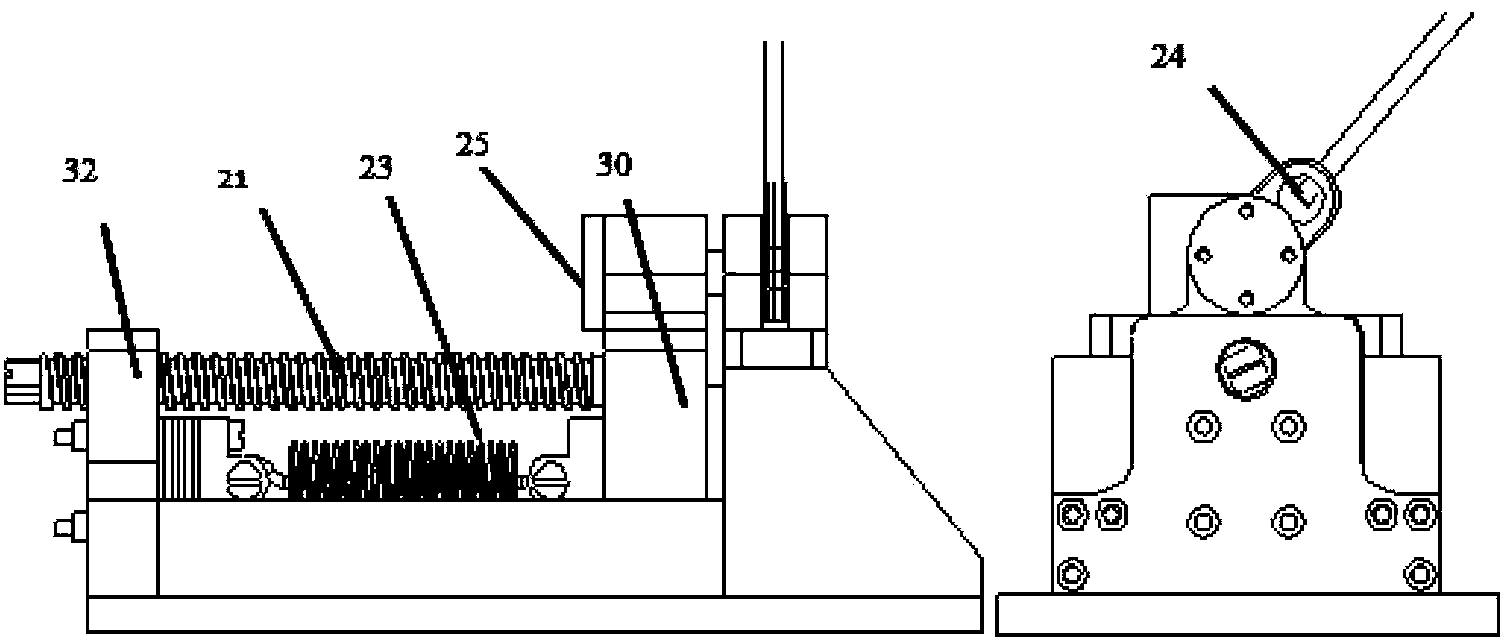
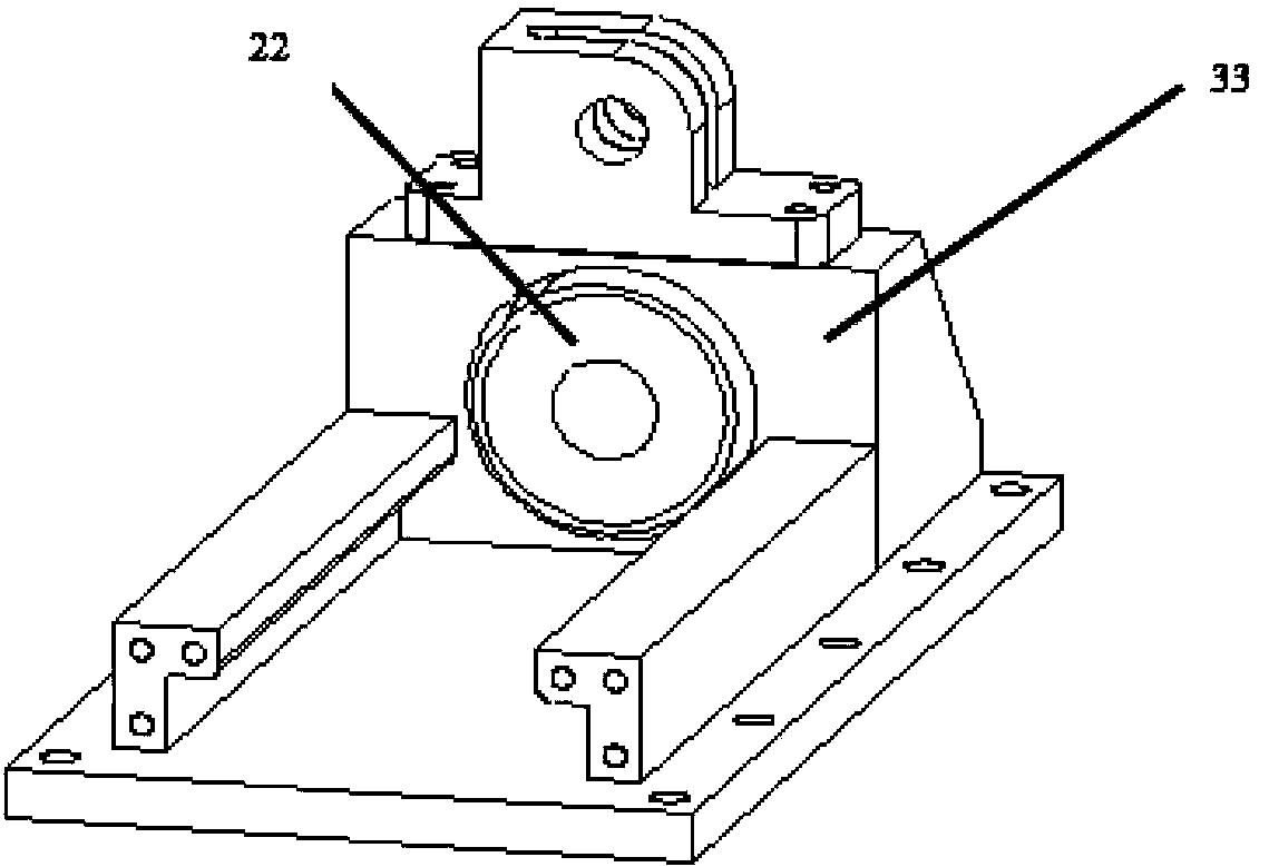
[0046] First of all, the clamping and releasing deployment mechanism 3 contained in the arrow-borne electric field stretching rod ground deployment experimental device of the present invention is identical in structure to the clamping and releasing mechanism contained in the electronic stretching rod (specifically as follows:figure 1 , figure 2 and Figure 5 shown), the clamp release mechanism is briefly described as follows: the clamp release mechanism includes: a base with a slideway, a nylon rope 2, an electromagnet 22, a tension spring 23, a ring 24, a cylindrical pin 25. Electrician pure iron 30, screw rod 21, screw r...


PUM


Abstract

The invention provides an arrow-loaded electric field stretching rod ground unfolding experimental device. The arrow-loaded electric field stretching rod ground unfolding experimental device comprises a rotating platform and a clamping releasing mechanism and is characterized by further comprising a microgravity simulation mechanism. The microgravity simulation mechanism further comprises a central pillar, steel wire ropes, a nylon rope and clamping hoops which are fixed on each section of an electric field stretching rod, wherein one end of each steel wire rope is pulled in a slant mode to be fixed on the central pillar, and the other end of each steel wire rope is connected with the clamping hoop of each section of the electric field stretching rod. One end of the nylon rope is connected with the clamping releasing mechanism, and the other end of the nylon rope is fixed on a pressing plate on the top of the electric field stretching rod. The central pillar comprises a plurality of sections of hollow cylinders, wherein flanges are arranged at two ends of each hollow cylinder. Every two sections of the cylinders are fixedly connected through a bolt, and each flange of each section of the cylinder is provided with a cylinder hole used for connecting one steel wire rope. One end of each steel wire rope is pulled in the slant mode to be fixed on the central pillar, and the other end of each steel wire rope is connected with the clamping hoop of each section of the stretching rod of the electric field stretching rod.

Description

technical field [0001] The invention relates to an experimental method for simulating on the ground the process of retracting, clamping, releasing, and deploying a sounding rocket extension rod, in particular to an experimental device for launching an arrow-borne electric field extension rod on the ground. Background technique [0002] The electric field extension rod mechanism is a key part of the sounding rocket. Whether the extension rod can be successfully deployed and the length of the extension directly affects whether the important payload electric field probe installed on the extension rod can work normally. It is also directly related to whether the payload can work properly. In order to ensure the reliability of the electric field extension rod deployment, the extension rod deployment test should be carried out on the ground to simulate the deployment process of the extension rod on the sounding rocket and test the reliability of the electric field extension rod de...

Claims


Application Information

Patent Timeline
Patent Type & Authority Patents(China)
IPC IPC(8): F42B15/08
Inventor 杨萱郑建华姜秀杰孟新
Owner NAT SPACE SCI CENT CAS
Why Eureka
Try Eureka