Experimental device for ground expansion of rocket-borne electronic extensible rod

An experimental device and electronic technology, applied in the direction of projectiles, self-propelled bombs, offensive equipment, etc., can solve the problem of not seeing the extension rod

Inactive Publication Date: 2013-03-27
NAT SPACE SCI CENT CAS
View PDF1 Cites 0 Cited by
  • Summary
  • Abstract
  • Description
  • Claims
  • Application Information

AI Technical Summary

Problems solved by technology

[0003] At present, there is no experimental device that can simulate the deployment process of the extension rod on the sounding rocket on the ground. This experimental device has successfully realized and completed the deployment experiment of a certain type of sounding rocket extension rod on the ground.

Method used


Image

  • Experimental device for ground expansion of rocket-borne electronic extensible rod
  • Experimental device for ground expansion of rocket-borne electronic extensible rod
  • Experimental device for ground expansion of rocket-borne electronic extensible rod

Examples


Embodiment Construction

[0023] The present invention will be further described below in conjunction with the accompanying drawings and embodiments.

[0024] (1) The present invention simulates the clamping and releasing states of the electronic extension rod under the specified rotational speed of the rocket.

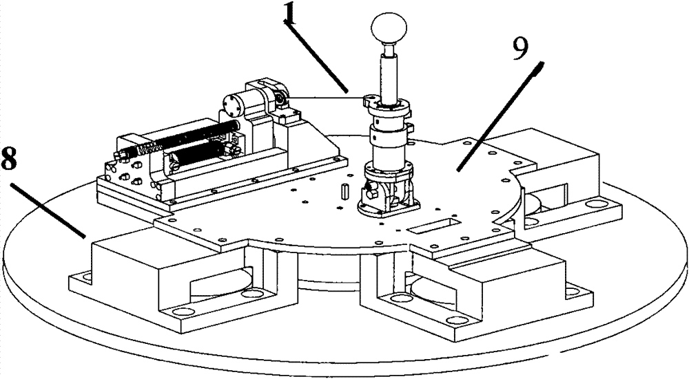
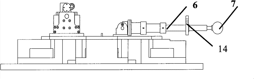
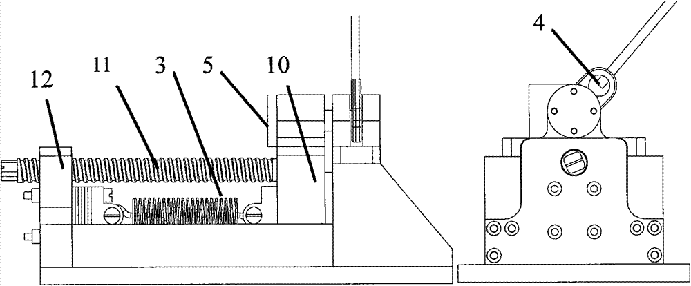
[0025] The working principle of the electronic extension rod expansion test is shown in Figure 1. Stretch bar tightens and releases and expands mechanism and is made up of nylon rope 1, electromagnet 2, extension spring 3, ring 4, cylindrical pin 5, electrician pure iron 10, screw rod 11, screw rod hole seat 12 and pin hole seat 13 etc. First, electrify the electromagnet 2, and the rotating screw 11 pushes the pure electric iron 10 to the electromagnet 2, so that the pure electric iron 10 and the electromagnet 2 are attracted together. At this time, the cylindrical pin 5 fixed on the pure electric iron 10 is inserted into the pin In the hole and the ring 4, the extension rod 6 is fixed by the...


PUM


Abstract

The invention provides an experimental device for ground expansion of a rocket-borne electronic extensible rod. The device is used for simulating control of expansion of the electronic extensible rod in the separation of a hood of a sounding rocket on the ground. The device comprises a base with a sliding way, an extension spring, a screw, an electromagnet, a circular ring, a cylindrical pin and electrical pure iron, wherein the base is fixed on a rotary platform; a screw hole seat and a pin hole seat are arranged at left and right ends of the base in opposite direction; the lower part of the screw hole seat is fixed with one end of the extension spring; a threaded hole for mounting the screw is formed on the upper part of the screw hole seat; the electromagnet is embedded into the lower part of the pin hole seat; the upper part of the pin hole seat is a limiting part; a pair of small holes is formed on the limiting part correspondingly; the circular ring is placed between the pair of small holes and fixed by inserting the cylindrical pin; the electrical pure iron is shaped like a Chinese character 'Tu'; a circular hole through which the cylindrical pin penetrates is processed on the upper half part of the electrical pure iron; the lower half part of the electrical pure iron is used for fixing the other end of the extension spring; and the bottom of the electrical pure iron is nested in the sliding way on the base.

Description

technical field [0001] The invention relates to an experimental method for simulating on the ground the process of retracting, clamping, releasing, and deploying a sounding rocket extension rod, in particular to an experimental device for launching an arrow-borne electronic extension rod on the ground. Background technique [0002] The electronic extension rod mechanism is a key component of the sounding rocket. Whether the extension rod can be deployed smoothly will directly affect whether the important payload electronic probe installed on the extension rod can work normally. Whether the load can work normally is also directly related. In order to ensure the reliability of the deployment of the electronic boom, an electronic boom deployment test should be carried out on the ground to simulate the deployment process of the boom on the sounding rocket and test the reliability of the deployment of the electronic boom. [0003] At present, there is no experimental device that...

Claims


Application Information

Patent Timeline
Patent Type & Authority Patents(China)
IPC IPC(8): F42B15/08
Inventor 杨萱姜秀杰孟新郑建华刘波
Owner NAT SPACE SCI CENT CAS
Why Eureka
Try Eureka