Vibration test device in liquid nitrogen temperature zone of cryogenic pressure accumulator for launch vehicle

A technology for vibration testing and launch vehicles, which is applied in vibration testing, measuring devices, and testing of machine/structural components.

Active Publication Date: 2016-06-01
BEIJING INST OF ASTRONAUTICAL SYST ENG +1
View PDF5 Cites 0 Cited by
  • Summary
  • Abstract
  • Description
  • Claims
  • Application Information

AI Technical Summary

Problems solved by technology

At present, the vibration test system at room temperature is relatively simple, and it has been unable to meet the vibration test requirements in the liquid nitrogen temperature zone of cryogenic accumulators.
[0003] At present, there are two main vibration test methods for pressure accumulators with this structure: one is to inject low-temperature helium gas to simulate the low-temperature working environment of the pressure accumulator. Although the low-temperature environment of the pressure accumulator can be realized, the pre-cooling time is long and cannot be simulated. The inertial impact effect of the liquid on the bellows; one is to use liquid nitrogen booster equipment to automatically pressurize liquid nitrogen into the accumulator shell. This method ensures that the accumulator is filled with liquid nitrogen instead of nitrogen gas, which is closer to reality. Working environment, but the liquid nitrogen pressurization equipment is large in size, occupies a large area and space, and the exhaust system must be at a high place, which poses a great safety hazard

Method used


Image

  • Vibration test device in liquid nitrogen temperature zone of cryogenic pressure accumulator for launch vehicle
  • Vibration test device in liquid nitrogen temperature zone of cryogenic pressure accumulator for launch vehicle

Examples


Embodiment Construction

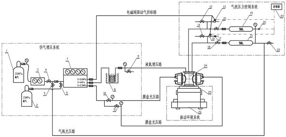
[0014] The present invention will be described in detail below in conjunction with the accompanying drawings. The test object of the present invention is a liquid nitrogen temperature zone vibration test system for a temperature accumulator used in a launch vehicle.

[0015] The test system of the present invention includes an air supply pressurization system, an air pillow pressure control system, and a vibration environment system; the vibration environment system includes a vibration table and a vibration tool; the low-temperature pressure accumulator is installed on the vibration table through the vibration tool; when the test starts , pour liquid nitrogen into the cryogenic pressure accumulator shell, and the gas supply pressurization system fills helium into the bellows of the cryogenic accumulator, so that the pressure in the bellows is consistent with the actual working pressure of the bellows; the air pillow pressure control system A gas cylinder is installed inside, ...


PUM


Abstract

A liquid nitrogen temperature zone vibration test device of a low temperature pressure accumulator for carrier rocket includes a supply air pressurization system, an air cushion pressure control system, and a vibration environment system. The vibration environment system comprises a vibration table and a vibration tooling; the low pressure accumulator is installed on the vibration table through the vibration tooling; at a beginning of a test, a liquid nitrogen is poured into a shell of the low temperature pressure accumulator; the supply air pressurization system injects helium into a diaphragm capsule of the low temperature pressure accumulator, so that a pressure in the diaphragm capsule is consistent with an actual working pressure of the diaphragm capsule; the air cushion pressure control system is internally provided with a gas cylinder; the gas cylinder is communicated with an inner cavity of the shell of the low temperature pressure accumulator; the supply air pressurization system fills the gas cylinder with the nitrogen, and fills the shell of the low temperature pressure accumulator with a gas-liquid mixed lower temperature nitrogen, so that the pressure in the gas cylinder is consistent with the pressure in the shell of the low temperature pressure accumulator; and in a vibration test, the air cushion pressure control system controls to maintains pressure stability in the shell of the low temperature pressure accumulator.

Description

technical field [0001] The invention belongs to a ground simulation test device for a launch vehicle, in particular to a liquid nitrogen temperature zone vibration test system for a low-temperature pressure accumulator used for a launch vehicle. Background technique [0002] The core stage cryogenic pressure accumulator is used to suppress the longitudinal vibration of the entire rocket caused by the vibration coupling between the rocket structure and the rocket engine and pipeline system, that is, POGO vibration, and is installed in front of the start valve of the oxidant pump port of the core stage engine. In order to simulate the actual flight conditions of the launch vehicle, it is necessary to carry out the liquid nitrogen temperature zone vibration test on the cryogenic accumulator during the ground simulation test of the launch vehicle. At present, the vibration test system at room temperature is relatively simple, and it has been unable to meet the vibration test req...

Claims


Application Information

Patent Timeline
Patent Type & Authority Patents(China)
IPC IPC(8): G01M7/02
Inventor 张连万邢力超王道连周炎赵涛程翔王跃平曹文利
Owner BEIJING INST OF ASTRONAUTICAL SYST ENG
Why Eureka
Try Eureka