
Device for regulating size of head of head lamp
A technology for adjusting devices and heads, which is applied in the direction of lighting devices, lighting auxiliary devices, lighting device components, etc., can solve the problems of increased frictional resistance between ropes or belts and hanging grooves, uncomfortable wearing, unsafe, etc., to achieve Guaranteed comfort, flexible size and tightness, reasonable design effect
- Summary
- Abstract
- Description
- Claims
- Application Information
AI Technical Summary
Problems solved by technology
Method used
Image

Examples
Embodiment Construction
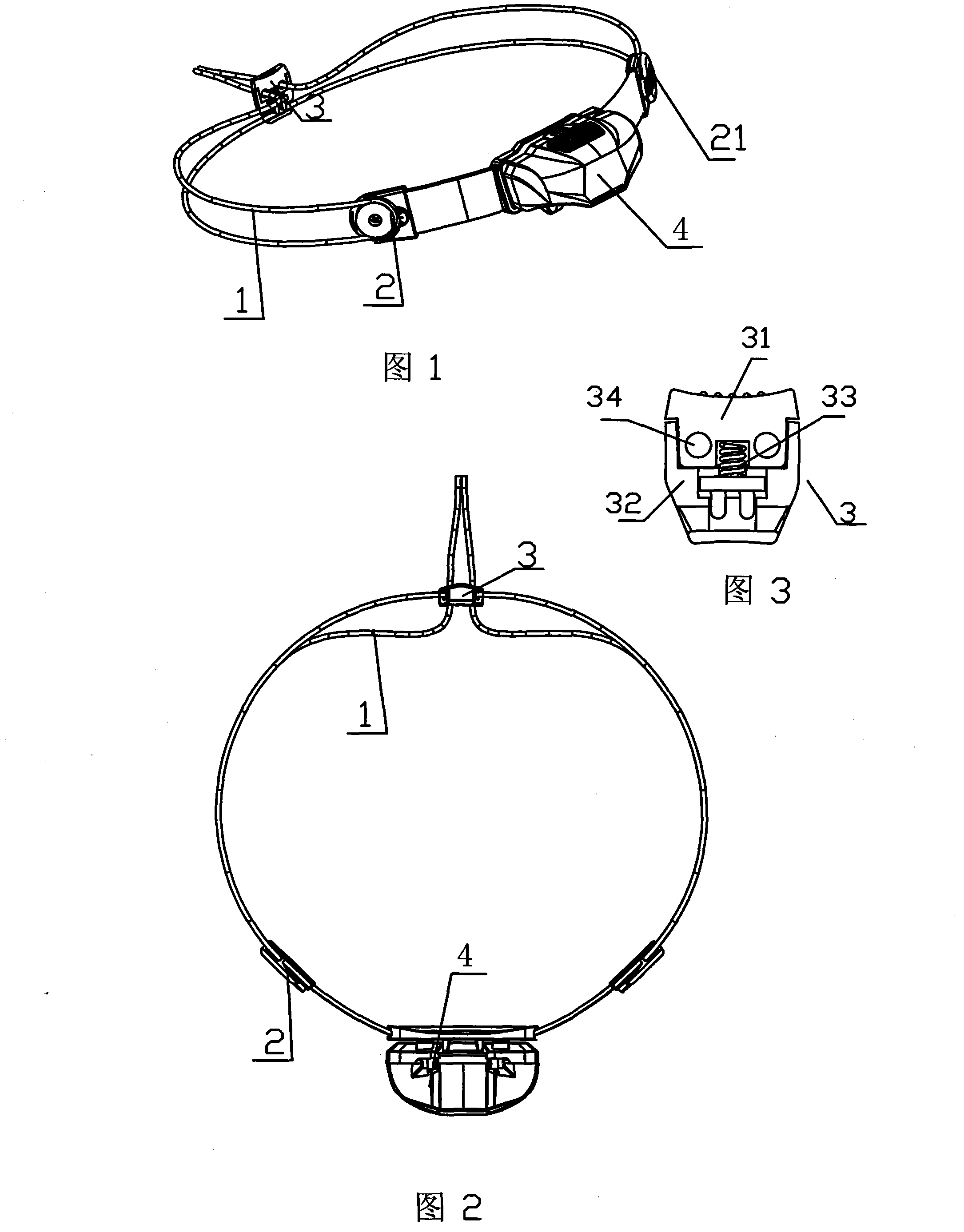
[0013] like figure 1 and figure 2 , image 3 As shown, a head size adjusting device for a headlight includes a rope or a belt 1 and a lamp cap 4, the two sides of the lamp cap 4 are provided with runners 2, the circumference of the runner 2 is provided with grooves, and the rope or belt 1 After wrapping around the groove of the runner 2, the two ends are passed through the holes of the regulator 3 respectively. A runner upper cover 21 is arranged outside the runner 2 . The shaft of the runner 2 is rotatably connected to both sides of the lamp cap 4 . The structure of the regulator 3 is as follows: it includes a first connecting part 31 and a second connecting part 32 that can move relatively therewith. Both the first connecting part 31 and the second connecting part 32 are provided with a rope or belt 1 to pass through. The through hole 34 of the first connecting part 31 and the second connecting part 32 is provided with a spring 33, when the first connecting part 31 is p...
PUM
 Abstract
Description
Claims
Application Information