Ultra-large-caliber stray light testing light source and control method thereof

A super-large aperture and stray light technology, which is applied in the direction of optical instrument testing, optical performance testing, machine/structural component testing, etc. Low cost, strong integrity and high test efficiency

Active Publication Date: 2019-01-18
BEIJING RES INST OF SPATIAL MECHANICAL & ELECTRICAL TECH
View PDF3 Cites 0 Cited by
  • Summary
  • Abstract
  • Description
  • Claims
  • Application Information

AI Technical Summary

Problems solved by technology

First of all, the existing stray light test system mainly uses light sources such as collimator and solar simulator to simulate parallel light sources, and an integrating sphere to simulate diffuse reflection light sources. The caliber of the optical system to be tested is often limited by the caliber of the simulated light source. For the optical system to be tested, the corresponding simulated light source is customized, and the light source has poor versatility; secondly, for the ultra-large-aperture stray light test system, it is necessary to customize the simulated light source such as a super-large-aperture collimator, solar simulator or integrating sphere, due to the limited processing and manufacturing Technological level, high cost, poor operability
Finally, the existing stray light test system can only realize the positioning of stray light paths at different angles and the test of stray light by rotating the simulated light source or optical system. During the test process, it is often necessary to replace the simulated light source to meet the test requirements, which often requires a huge rotating mechanism , the test accuracy is low, and the test process is cumbersome

Method used


Image

  • Ultra-large-caliber stray light testing light source and control method thereof
  • Ultra-large-caliber stray light testing light source and control method thereof

Examples


specific Embodiment approach

[0038] The present invention is a super-large-diameter stray light test light source, which can solve the problem that the ultra-large-caliber stray light test simulation light source is difficult to process at the present stage, and realize the mutual conversion of different types of stray light simulation light sources between diffuse reflection light source and parallel light source, and can be applied to different calibers at the same time. The stray light test of the optical system to be tested adopts an automatic control system, which improves the accuracy of the stray light test. The specific implementation method is:

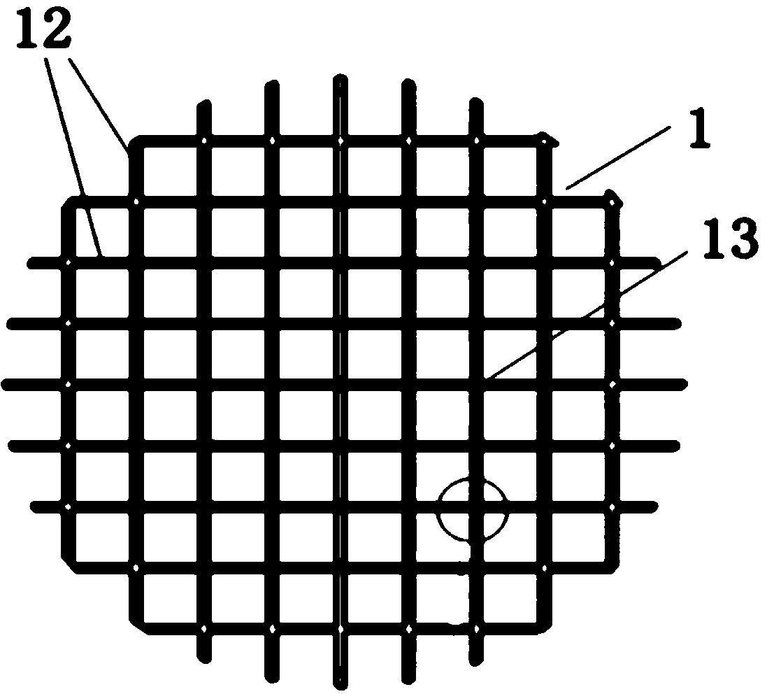
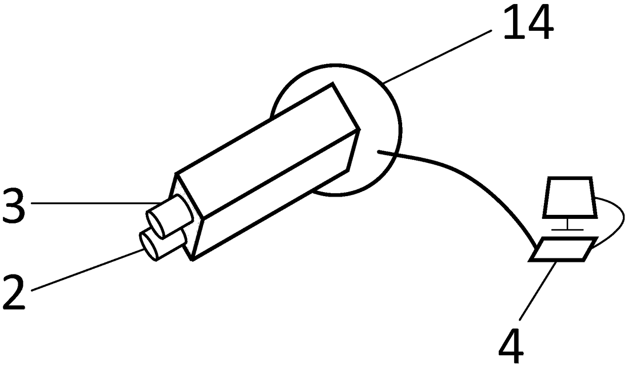
[0039] Such as figure 1 As shown, a super-large-aperture stray light test light source is composed of a truss-type curved surface support 1, a collimated light source 2, a scattered light source 3, and a control system 4; Each network node 13 in the network places a universal adjustment device 14;

[0040] Such as figure 2 As shown, the parallel ligh...


PUM


Abstract

Disclosed is an ultra-large-caliber stray light testing light source and a control method thereof. The ultra-large-caliber stray light testing light source is realized through a truss type curved surface support, a light source and a control system. The truss type curved surface support is integrally presented as a spherical or secondary curved surface shape; a transverse and transverse network isformed by adopting a truss type structure, and a universal adjusting device is placed on each network node. Two light sources are placed on each universal adjusting device, wherein one of the light sources is a parallel light source, and the other is a scattered light source with a certain scattering angle. When a collimating light source is used, the emergent light of all the light sources formsan approximately parallel light beam; when a scattered light source is used, the emergent light of all the light sources forms an approximate Lamb light source. When the stray light test is carried out, the control system can control each universal adjusting device, and the light beams with different emergent angles can be adjusted; the control system can control the on and off and the intensityof each light source at the same time, so that the size and the intensity of the light beams can be adjusted. The novel stray light testing light source is small in scale and convenient to machine andmanufacture, can be applied to stray light testing of an optical system, and is particularly suitable for ultra-large-caliber stray light testing.

Description

technical field [0001] The invention relates to a super-large-diameter stray light test light source and a control method thereof, and belongs to the technical field of super-large-diameter light testing. Background technique [0002] The stray light test mainly locates the stray light path of the optical system and tests the stray light suppression level by simulating the incident angle and light intensity of the stray light source. First of all, the existing stray light test system mainly uses light sources such as collimator and solar simulator to simulate parallel light sources, and an integrating sphere to simulate diffuse reflection light sources. The caliber of the optical system to be tested is often limited by the caliber of the simulated light source. For the optical system to be tested, the corresponding analog light source is customized, and the light source has poor versatility; secondly, for the ultra-large-aperture stray light test system, it is necessary to c...

Claims


Application Information

Patent Timeline
Patent Type & Authority Applications(China)
IPC IPC(8): G01M11/02
CPCG01M11/00
Inventor 李洋张庭成廖志波徐彭梅李永强胡永力赵野
Owner BEIJING RES INST OF SPATIAL MECHANICAL & ELECTRICAL TECH
Why Eureka
Try Eureka