[0002] Enhancements in
automotive safety systems over the past several decades have provided dramatic improvements
in vehicle occupant protection. Presently available motor vehicles include an array of such systems, including
inflatable restraint systems for protection of occupants from frontal impacts, side impacts, and roll-over conditions. Advancements in restraint belts and vehicle interior
energy absorbing systems have also contributed to enhancements in safety. Many of these systems must be deployed or actuated in a non-reversible manner upon the detection of a vehicle impact to provide their beneficial effect. Many designs for such sensors are presently used to detect the presence of an impact or roll-over condition as it occurs.
[0003] Attention has been directed recently to providing deployable systems external to the vehicle. For example, when an impact with a
pedestrian or bicyclist is imminent, external airbags can be deployed to reduce the severity of impact between the vehicle and
pedestrian. Collisions with bicyclists and pedestrians account for a significant number of motor vehicle fatalities annually. Another function of an external airbag may be to provide greater compatibility between two vehicles when an impact occurs. While an effort has been made to match bumper heights for passenger cars, there remains a disparity between bumper heights, especially between classes of passenger vehicles, and especially involving collisions with heavy trucks. Through deployment of an external airbag system prior to impact, the bag can provide enhancements in the mechanical interaction between the vehicles in a manner which provides greater
energy absorption, thereby reducing the severity of injuries to vehicle occupants.
[0005]
Radar detection systems have been studied and employed for motor vehicles for many years.
Radar systems for motor vehicles operate much like their
aviation counterparts in that a
radio frequency signal, typically in the
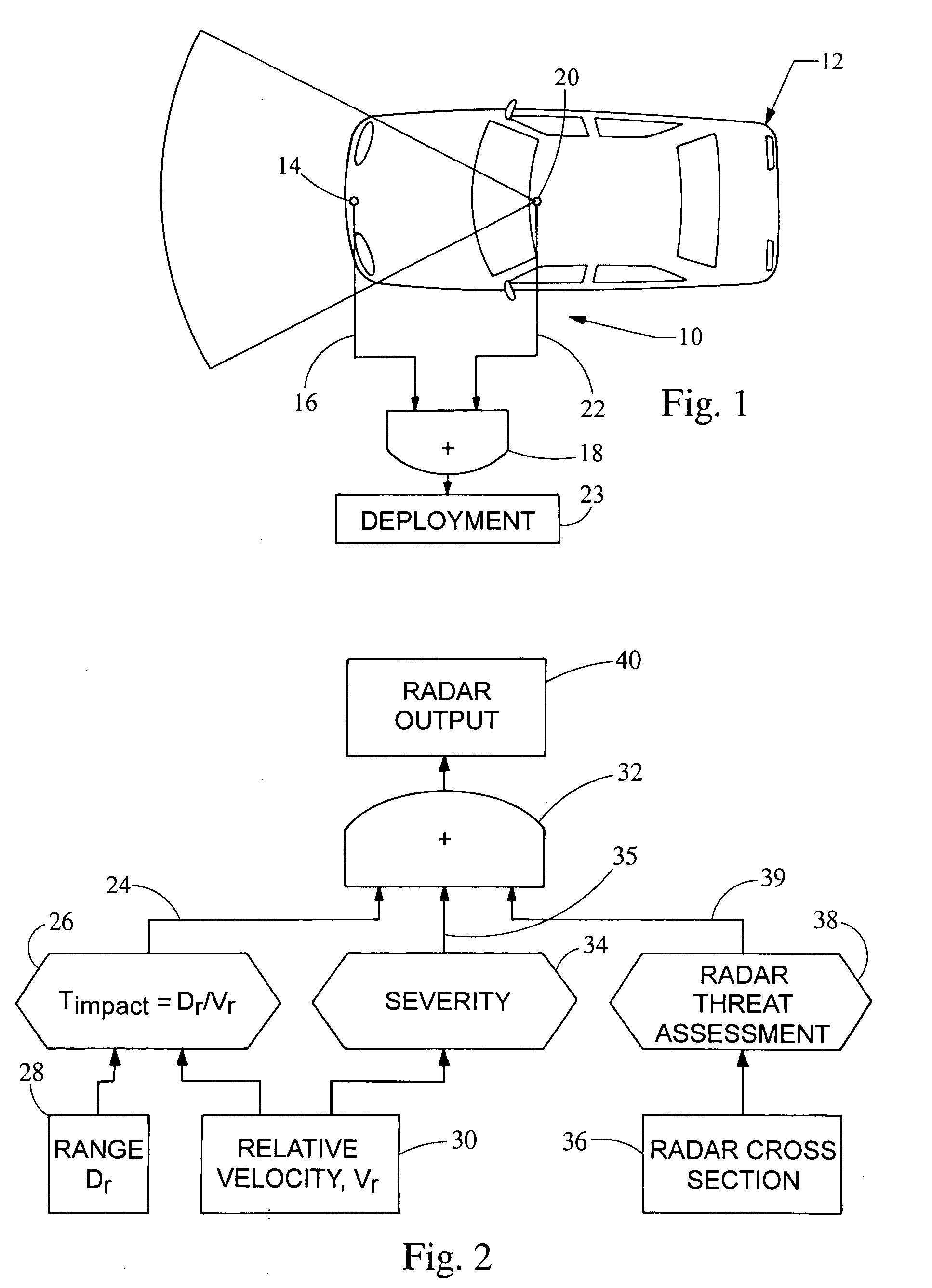
microwave region, is emitted from an antenna on the vehicle and the reflected-back signal is analyzed to reveal information about the reflecting target. Such systems have been considered for use in active braking systems for motor vehicles, as well as obstacle detection systems for vehicle drivers. Radar sensing systems also have applicability in deploying external airbags. Radar sensors provide a number of valuable inputs, including the ability to detect the range to the closest object with a high degree of accuracy (e.g. 5 cm). They can also provide an output enabling measurement of closing velocity to a target with high accuracy. The
radar cross section of the target and the characteristics of the return signal may also be used as a means of characterizing the target.
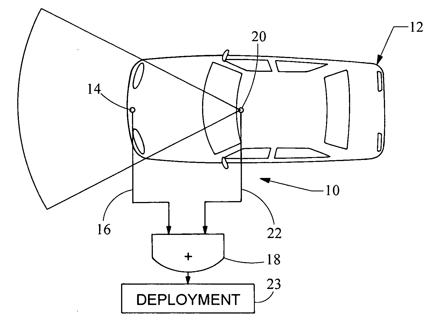
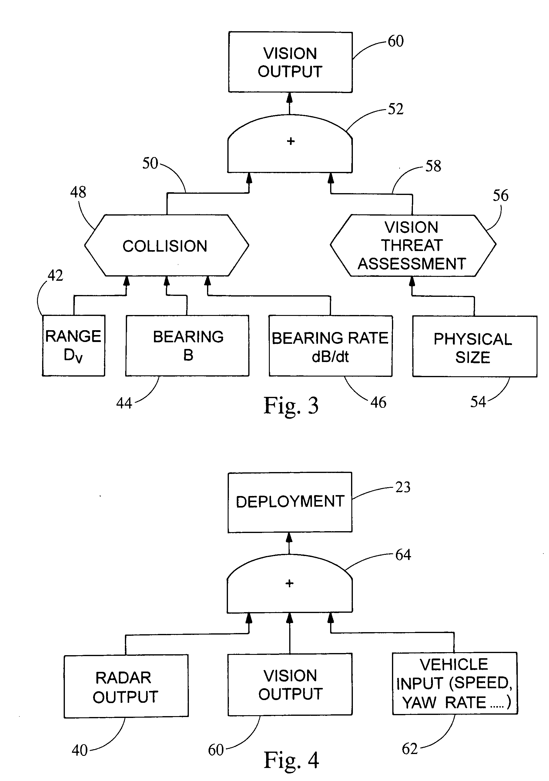
[0007] In accordance with this invention, data received from a radar sensor is processed along with vision data obtained from a
vision sensor. The
vision sensor may be a stereo or a three-dimensional vision system that is mounted to the vehicle. The vision sensor can be a pair of 2 dimensional cameras that are designed to work as a
stereo pair. By designing a
stereo pair, the set of cameras can generate a 3 dimensional image of the scene. The vision subsystem can be designed with a
single camera used in conjunction with modulated light to generate a 3 dimensional image of the scene. This 3 dimensional image is designed to overlap the radar beams so that objects will be sensed within the same area. Both the radar and 3 dimensional vision sensors measure a range to the sensed object as one of their sensed features. Since this is the common feature, it is used to correlate information from each sensor. This information correlation is important for correct fusion of the independently sensed information especially in a
multiple target environment. The fusion of radar and vision sensing systems data provide a highly reliable non-contact sensing of an impending collision. The
fusion mechanism is the overlap of radar range and vision depth information. The invention functions to provide a signal that an impact is imminent. This signal of an impending
crash is generated from an object approaching the vehicle from any direction in which the
sensor system is installed. In addition to an indication of impending
crash, the sensor system will also indicate the potential intensity of the
crash. The exact time of impact, and the direction of the impact is also indicated by this fused sensor system. The intensity of the crash is determined by the relative size of the striking object, and the speed with which the object is approaching the host vehicle. The time, and direction of the impact is determined by repeated measurements of the object's position. This sequence of position data points can be used to compute an objects trajectory, and by comparing this trajectory with that of the host vehicle, a point of impact can be determined. The closing velocity can also be determined by using the position data and trajectory calculations. The
advantage of this invention is the high reliability the
sensor fusion combination provides.
[0008] Additional benefits and advantages of the present invention will become apparent to those skilled in the art to which the present invention relates from the subsequent description of the preferred embodiment and the appended claims, taken in conjunction with the accompanying drawings. These benefits include being able to begin deploying the airbags sooner so their deployment speed can be reduced. With more time to inflate, the airbag size can be increased. With advanced notice of an impending crash, the seatbelts can be tightened by triggering an electric pre-pretensioner. Tightening the seatbelts increases their effectiveness. The seating position and headrest position can be modified, based on advanced crash information to increase their effectiveness in a variety of crash scenarios. Additional time to deploy enables safety devices that are slower in comparison to today's airbags. Electric knee
bolster extenders can be enabled to help hold the occupant in position during a crash. Advance warning also enables the windows and
sunroof to close to further increase crash safety. External structures can be modified with advance notice of an impending crash. Structures such as extendable bumpers and external airbags can be deployed to further reduce the crash forces transmitted to the vehicle's occupants.BRIEF DESCRIPTION OF THE DRAWINGS

