Temperature difference driven cooling device for on-board energy storage system

A technology of energy storage system and cooling device, which is applied in the direction of vehicle energy storage, power device, and the arrangement of cooling combination of power device, etc. It can solve the problems of increasing energy consumption and affecting battery life, achieve good cooling effect, and make up for air energy The effect of low density and low cost

Inactive Publication Date: 2016-01-20
QINGDAO UNIV
View PDF10 Cites 0 Cited by
  • Summary
  • Abstract
  • Description
  • Claims
  • Application Information

AI Technical Summary

Problems solved by technology

[0006] The purpose of the present invention is to overcome and solve the problem that air cooling and additional cooling means in the prior art need to increase energy consumption and affect the battery life, and provide a more effective cooling device for vehicle-mounted energy storage systems, which is used for vehicle-mounted energy storage systems A thermoelectric power generation driven air amplification device for cooling

Method used


Image

  • Temperature difference driven cooling device for on-board energy storage system
  • Temperature difference driven cooling device for on-board energy storage system
  • Temperature difference driven cooling device for on-board energy storage system

Examples


Embodiment 1

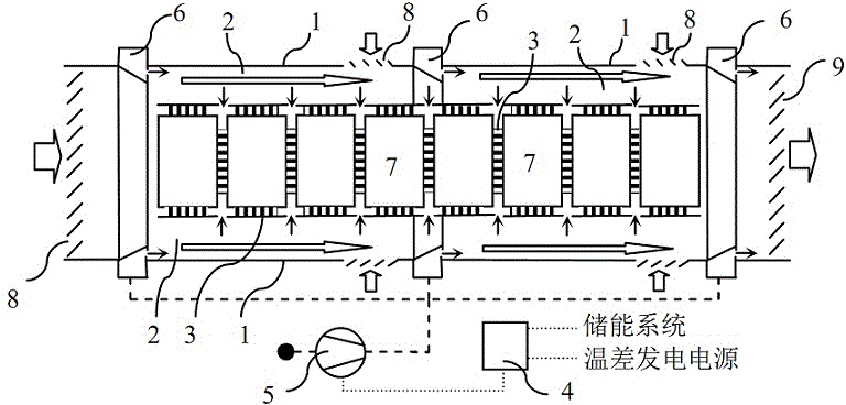
[0022] Such as figure 1 Shown is a schematic diagram of the structure of the serial ventilation cooling device, including the cabinet 1, the cooling air duct 2, the thermoelectric power supply 3, the power management unit 4, the compressed air generator 5, the air amplifier 6, the energy storage system 7, the adjustable Waterproof air inlet 8 and adjustable waterproof air outlet 9. The box body 1 is cylindrical, in which the energy storage system 7 is placed. The cooling air channel 2 is the circulation channel formed between the box body 1 and the energy storage system 7. An air amplifier 6 is installed at the head end, the end and the middle of the box body 1. , the upstream of the air amplifier 6 is provided with an adjustable waterproof air inlet 8, the terminal air amplifier 6 of the box body 1 is provided with an adjustable waterproof air outlet 9, the air flow channel of the air amplifier 6 is connected to the cooling air channel 2 and overlaps, and the thermoelectric p...

Embodiment 2

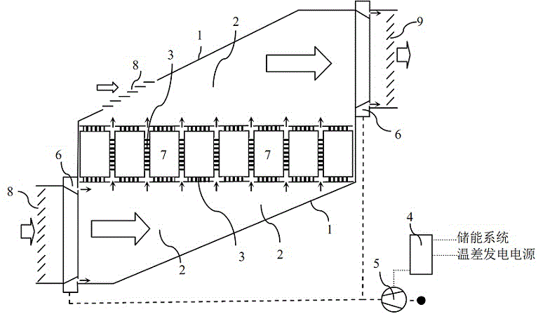
[0025] Such as image 3 Shown is a schematic structural diagram of a parallel ventilation cooling device, including a cabinet 1, a cooling air duct 2, a thermoelectric power supply 3, a power management unit 4, a compressed air generator 5, an air amplifier 6, an energy storage system 7, an adjustable waterproof The air inlet 8 and the adjustable waterproof air outlet 9, the energy storage system 7 is placed in the box body 1, and the head and end of the box body 1 are provided with gas collection cylinders to evenly distribute the air flow to each energy storage system unit 7. The cooling air channel 2 is a circulation channel formed between the gas collection cylinder and the energy storage system 7. An air amplifier 6 is installed at the head end and the end of the box body 1, and an adjustable waterproof air inlet 8 is installed upstream of the air amplifier 6. An adjustable waterproof air outlet 9 is set downstream of the air amplifier 6 at the end position. The air flow ...


PUM


Abstract

The invention relates to a differential-temperature-driven vehicular energy storage system cooling device comprising a box, cooling air passages, a differential temperature generation source, a power management unit, a compressed air generator and an air amplifier. Power is generated by temperature difference between an energy storage system unit chamber and the environment thereof as well as an energy storage unit and the environment thereof, the compressed air generator is driven by the power, compressed air is guided and amplified so as to obtain large-flow cooling air through the air amplifier, and the cooling air flows through the energy storage system to achieve cooling. The differential-temperature-driven vehicular energy storage system cooling device is simple, easy to use, safe, and low in cost; through differential temperature drive, the vehicle energy consumption is not increased, and cruising power is improved while effective cooling is guaranteed; through the air amplifier, the defect that air energy is low in density is overcome and the cooling effect is better; the larger the cooling load is, the larger the temperature difference is, the higher the differential temperature driving force is and the higher the cooling power is, so that a self-feedback system is formed; the differential-temperature-driven vehicular energy storage system cooling device is applicable to electric vehicles and hybrid vehicles.

Description

technical field [0001] The invention relates to a cooling device for a vehicle-mounted energy storage system, in particular to a temperature-difference-driven air amplification cooling device for the vehicle-mounted energy storage system, and belongs to the technical field of cooling. Background technique [0002] In recent years, vehicles such as hybrid electric vehicles and pure electric vehicles have been put into use more and more, all of which need to be equipped with energy storage systems with sufficient capacity, which also brings problems in the layout and cooling of energy storage systems. At present, the structure of the energy storage system is huge, and it is mainly arranged in the car and on both sides of the car body or on the roof. The former is limited by the car body structure and cannot meet the needs of customers for fully utilizing the car interior space and different forms of car body structures; the energy storage system is arranged in The roof is the ...

Claims


Application Information

Patent Timeline
Patent Type & Authority Patents(China)
IPC IPC(8): B60K11/06B60L11/18
CPCY02T10/70
Inventor 郑艺华刘君
Owner QINGDAO UNIV
Why Eureka
Try Eureka