Method for shaping circular beams into ring beams

A ring beam and beam shaping technology, which is applied in the field of non-imaging optics, can solve the problems of optical antenna energy loss, etc., and achieve the effects of improving light energy utilization, eliminating secondary mirror occlusion, and reducing loss

Inactive Publication Date: 2013-09-18
HARBIN INST OF TECH
View PDF5 Cites 8 Cited by
  • Summary
  • Abstract
  • Description
  • Claims
  • Application Information

AI Technical Summary

Problems solved by technology

[0006] The present invention aims to solve the problem of energy loss caused by optical antennas, and provides a method for realizing the shaping of circular light beams into ring-shaped light beams, improving the utilization rate of light energy

Method used


Image

  • Method for shaping circular beams into ring beams
  • Method for shaping circular beams into ring beams
  • Method for shaping circular beams into ring beams

Examples


specific Embodiment approach 1

[0041] Specific Embodiment 1: A method for shaping a circular beam into a circular beam according to this embodiment is implemented in the following steps:

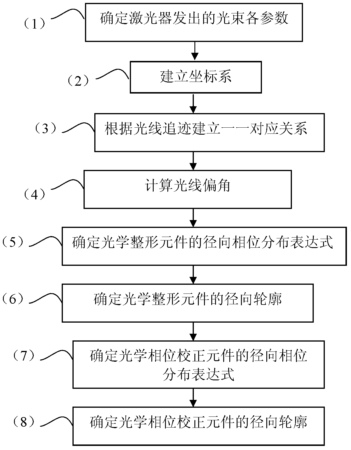
[0042] The specific steps of the design method for shaping a circular beam into a ring beam are as follows:

[0043] (1) if Figure 9 , determine the diameter D0 of the circular beam, the diameters D1 and D2 of the inner and outer rings of the annular beam, and the distance L between the two optical elements: if the apertures of the primary mirror and the secondary mirror are d 1 、d 2 , if the magnification of the antenna is T, then

[0044] D 1 ≤ d 1 / T D 2 ≥ d 2 / T ...


PUM


Abstract

The invention discloses a method for shaping circular beams into ring beams, relates to the field of nonimaging optics, and aims solve the problem of energy loss caused by optical antennas. The method for shaping the circular beams into the ring beams includes steps of 1), determining each parameter of beams emitted by a laser; 2), establishing a coordinate system; 3), establishing one-to-one corresponding relation according to ray traces; 4), calculating deflections of the rays; 5), determining a radial phase distribution formula of an optical shaping component; 6), determining radial profiles of the optical shaping component; 7), determining a radial phase distribution formula of an optical phase correcting component; 8), determining radial profiles of the optical phase correcting component. The method for shaping the circular beams into the ring beams is applicable to the field of optics.

Description

technical field [0001] The invention relates to the field of non-imaging optics, in particular to a method for shaping a circular light beam into a ring-shaped light beam. Background technique [0002] In systems such as lidar and free-space laser communication, the beam expansion collimation of the optical transmission system generally uses a double-reflection Cassegrain optical antenna, which inevitably results in loss of light energy due to occlusion of the secondary mirror. , and since the light intensity of the light source is a general Gaussian distribution, this loss is more obvious. [0003] A typical optical transmission system is mainly composed of a laser (1), a collimator lens group (2) and a Cassegrain optical antenna composed of a primary mirror (3) and a secondary mirror (4), such as figure 2 . Among them, the Cassegrain optical antenna is actually an afocal telescope structure, which is composed of a primary mirror and a secondary mirror placed coaxially. ...

Claims


Application Information

Patent Timeline
IPC IPC(8): G02B27/09
Inventor 胥全春俞建杰杜继东周彦平韩琦琦
Owner HARBIN INST OF TECH
Why Eureka
Try Eureka