Check patentability & draft patents in minutes with Patsnap Eureka AI!

Cutting Fixture

A fixture and channel steel technology, applied in the field of mechanical processing, can solve the problems of affecting product quality, non-vertical cutting surface, time-consuming and labor-intensive problems, and achieve the effect of convenient steel, product quality assurance and work efficiency improvement

Inactive Publication Date: 2016-01-06
宋云昌
View PDF5 Cites 1 Cited by
  • Summary
  • Abstract
  • Description
  • Claims
  • Application Information

AI Technical Summary

Problems solved by technology

[0002] Some small and medium-sized machinery factories do not have large cutting machines, only grinders are used to cut steel such as steel pipes and angle irons. There are two problems when using grinders to cut long steel in batches. One end of the self-weight will touch the ground, and the other end will be tilted, causing the cutting surface to be non-vertical and affecting product quality; 2. When cutting steel materials of the same specification in batches, the length needs to be measured before cutting each piece, which is time-consuming and laborious, which is very inconvenient

Method used


Image

  • Cutting Fixture
  • Cutting Fixture

Examples


Embodiment 1

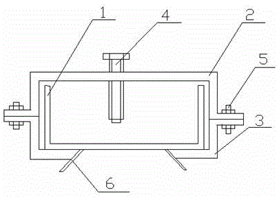
[0015] Such as figure 1 and figure 2 The cutting fixture includes a channel steel 1, the opening of the channel steel 1 is upward, two sets of support feet 6 are welded below the channel steel 1, the plane of the notch of the channel steel 1 is the same as the height of the grinder table, and one end of the channel steel 1 is connected to the grinding wheel. The machine is connected, and a limit device is provided on the channel steel 1 away from the direction of the grinder. The limit device is composed of an upper platen 2 and a lower platen 3 connected by a screw 5. The top surface of the upper platen 2 is provided with a screw hole. Limit bolt 4 is installed inside. When cutting the steel pipe, first choose a clamp that is one size smaller than the diameter of the steel pipe so that the steel pipe cannot roll. After connecting with the grinder, put the steel pipe on the channel steel. horizontal position.

[0016] According to the length of the steel pipe to be cut, mo...

Embodiment 2

[0019] As an improvement of the present invention, the cutting process is the same as in embodiment 1, except that two screw holes in the horizontal direction are provided on the top surface of the upper platen, and bolts are installed in the two screw holes. Among them, the limit bolt 4 is far away from the grinder, and the compression bolt 7 is close to the grinder. Before cutting, loosen the compression bolt 7, and after the steel pipe sticks to the limit bolt 4, tighten the compression bolt 7, and then start cutting. This fixes the steel pipe for better cutting results.


PUM


Abstract

The invention discloses a cutting fixture. The cutting fixture comprises a steel channel 1 with an upward opening, two groups of support feet 6 are welded below the steel channel 1, the height of the concave plane of the steel channel 1 is equal to that of the surface of a grinding machine, one end of the steel channel 1 is connected with the grinding machine, a limiting device is arranged at a position of the steel channel 1, which is far away from the grinding machine direction, the limiting device is formed by connecting an upper pressing board 2 with a lower pressing board 3 through a bolt 5, a bolt hole is formed in the top surface of the upper pressing board 2, and a limiting bolt 4 is arranged in the bolt hole. When a steel tube is cut, the steel tube is placed on the steel channel horizontally, the limiting device is moved to a corresponding position according to the length of the steel tube to be cut, the steel tube is pushed to the limiting device, cutting is started, cut steel tube cuts are vertical, the length of the steel tube is standard, the working efficiency can be improved, and the product quality can be guaranteed.

Description

technical field [0001] The invention relates to a cutting fixture, which belongs to the field of mechanical processing. Background technique [0002] Some small and medium-sized machinery factories do not have large cutting machines, only grinders are used to cut steel such as steel pipes and angle irons. There are two problems when using grinders to cut long steel in batches. One end of the self-weight will touch the ground, and the other end will be tilted, causing the cutting surface to be non-vertical and affecting product quality; 2. When cutting steel materials of the same specification in batches, the length needs to be measured before cutting each piece, which is time-consuming and laborious, which is very inconvenient. Contents of the invention [0003] In order to solve the above problems, the present invention discloses a cutting jig. [0004] To achieve the above object, the technical scheme of the present invention is as follows: [0005] The cutting fixture...

Claims


Application Information

Patent Timeline
Patent Type & Authority Patents(China)
IPC IPC(8): B24B27/06
Inventor 宋云昌
Owner 宋云昌
Features
  • R&D
  • Intellectual Property
  • Life Sciences
  • Materials
  • Tech Scout
  • Unparalleled Data Quality
  • Higher Quality Content
  • 60% Fewer Hallucinations
Learn More