Multi-frequency plane printed antenna comprising protruded floor and applied to mobile terminal

A mobile terminal and floor technology, which is applied in the direction of antenna, antenna grounding device, antenna grounding switch structure connection, etc., can solve the problems of antenna performance deterioration and achieve the effect of reducing processing and manufacturing costs

Active Publication Date: 2013-10-09
TSINGHUA UNIV
View PDF4 Cites 10 Cited by
  • Summary
  • Abstract
  • Description
  • Claims
  • Application Information

AI Technical Summary

Problems solved by technology

If electronic equipment is placed in the remaining clearance area, especially electronic devices containing metal parts, the performance of the antenna will inevitably deteriorate to a certain extent

Method used


Image

  • Multi-frequency plane printed antenna comprising protruded floor and applied to mobile terminal
  • Multi-frequency plane printed antenna comprising protruded floor and applied to mobile terminal
  • Multi-frequency plane printed antenna comprising protruded floor and applied to mobile terminal

Examples


Embodiment Construction

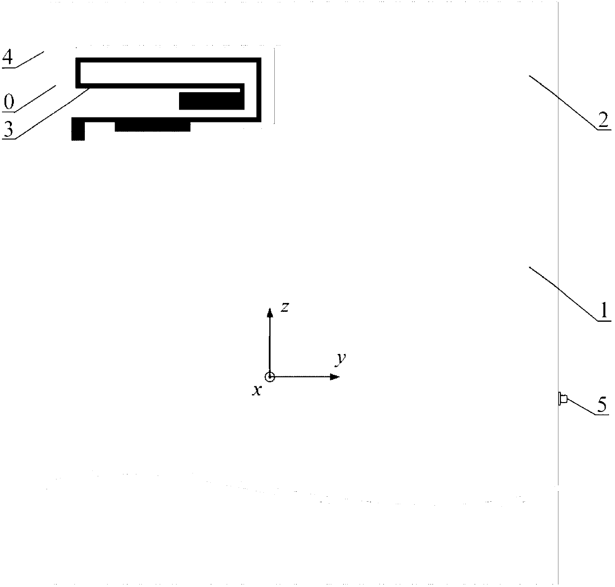
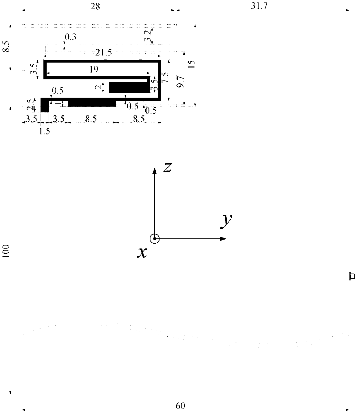
[0031] The present invention provides a multi-frequency planar printed antenna with a protruding floor applied to a mobile terminal. The specific implementation scheme is as follows:

[0032] The structure of each part of the planar printed antenna is printed on a dielectric board 0 using a double-layer printed circuit board process. The main floor 1 printed on the lower back of the dielectric board 0 is used to simulate the circuit part of the circuit board. Printed on the back of the media board 0, located on the upper right of the main floor 1 and connected to the protruding floor 2 of the main floor 1, for electronic equipment that may be needed, such as digital cameras, speakers, data ports, power supply and headphone jacks, etc. Space for placement. The main part of the antenna consists of the excitation branch 3 printed on the front of the dielectric board 0 and the parasitic ground branch 4 printed on the back of the dielectric board 0. The antenna's low frequency band ...


PUM


Abstract

The invention discloses a multi-frequency plane printed antenna comprising a protruded floor and applied to a mobile terminal and belongs to the technical field of mobile terminal antennas. The multi-frequency plane printed antenna is characterized in that two resonance structures, namely a simulation branch and a parasitism land branch are utilized to select and combine all resonance modes which are simulated so as to obtain broadband and multi-frequency characteristics. A coaxial probe feeding manner is utilized to improve the reliability of test results, and impedance matching is performed by loading an adjusting piece. In addition, with the protruded floor structure, under the condition that acceptable antenna performance is ensured, placing spaces are provided for electronic equipment such as a camera, a loudspeaker, a data interface, a power supply and an earphone interface, wherein the electronic equipment possibly needs to be placed. The area of a clearance zone occupied by the multi-frequency plane printed antenna on a circuit board is only 15mm*28.3mm, a -6dB impedance bandwidth of the multi-frequency plane printed antenna can effectively cover work frequency bands of GSM 850, GSM 900, DCS, PCS, UMTS, LTE 2300, 2.4-GHz WLAN, LTE 2500 and the like.

Description

Technical field [0001] The invention belongs to the field of small multi-frequency antenna design, and relates to a multi-frequency planar antenna with a protruding floor and printed on a double-layer PCB board applied to a mobile terminal. Background technique [0002] With the rapid development of mobile communications, mobile terminals are required to have richer service functions and more beautiful appearance designs. At the same time, to achieve global roaming, it needs to meet the frequency band requirements of different communication protocols in different regions. Therefore, antennas used in mobile terminals It is necessary to cover as many communication frequency bands as possible with limited size. The existing WWAN (Wireless Wide Area Network) system requires antennas to cover GSM850 (824-894MHz), GSM900 (880-960MHz), DCS (17101-880MHz), PCS (1850-1990MHz), UMTS (1920-2170MHz) and other communications Frequency band. To achieve ubiquitous wireless Internet access, th...

Claims


Application Information

Patent Timeline
Patent Type & Authority Applications(China)
IPC IPC(8): H01Q1/38H01Q1/48H01Q1/50H01Q5/01H01Q5/10
Inventor 王尚杜正伟
Owner TSINGHUA UNIV
Why Eureka
Try Eureka