Multi-point touch identification method for infrared touch screen

An infrared touch screen and multi-touch technology, applied in the direction of instruments, electrical digital data processing, data processing input/output process, etc., can solve the problem that the number of LED lights on the X-axis and Y-axis is very different, and the touch point cannot be accurately identified And other problems, to achieve the effect of fast operation

Inactive Publication Date: 2013-10-23
陈云波
View PDF5 Cites 19 Cited by
  • Summary
  • Abstract
  • Description
  • Claims
  • Application Information

AI Technical Summary

Problems solved by technology

Generally speaking, this method can accurately determine the position of the real touch point, but because the number of LED lights on the X-axis and Y-axis is very different, if there is an error of an LED light on the X-axis or Y-axis, after t

Method used


Image

  • Multi-point touch identification method for infrared touch screen
  • Multi-point touch identification method for infrared touch screen
  • Multi-point touch identification method for infrared touch screen

Examples


Embodiment Construction

[0023] The specific implementation case of the present invention is described below in conjunction with accompanying drawing:

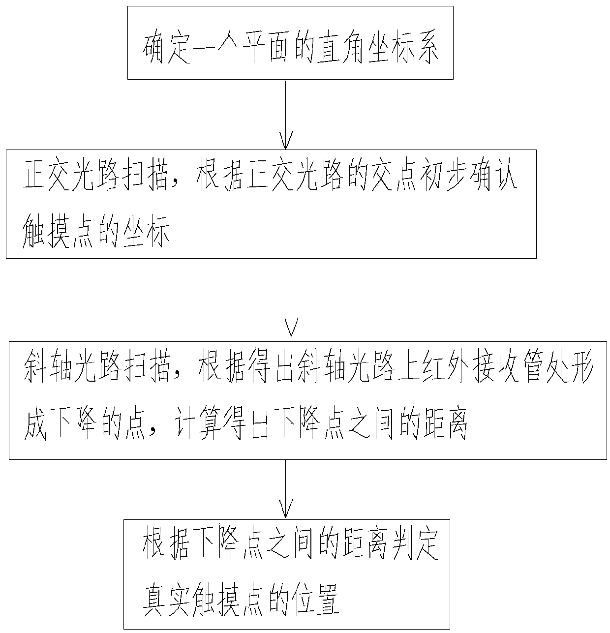
[0024] Such as figure 1 Shown: Infrared touch screen multi-touch recognition method, including steps:

[0025] (1) Determine a plane Cartesian coordinate system with one corner as the coordinate origin of the entire screen of the infrared touch screen.

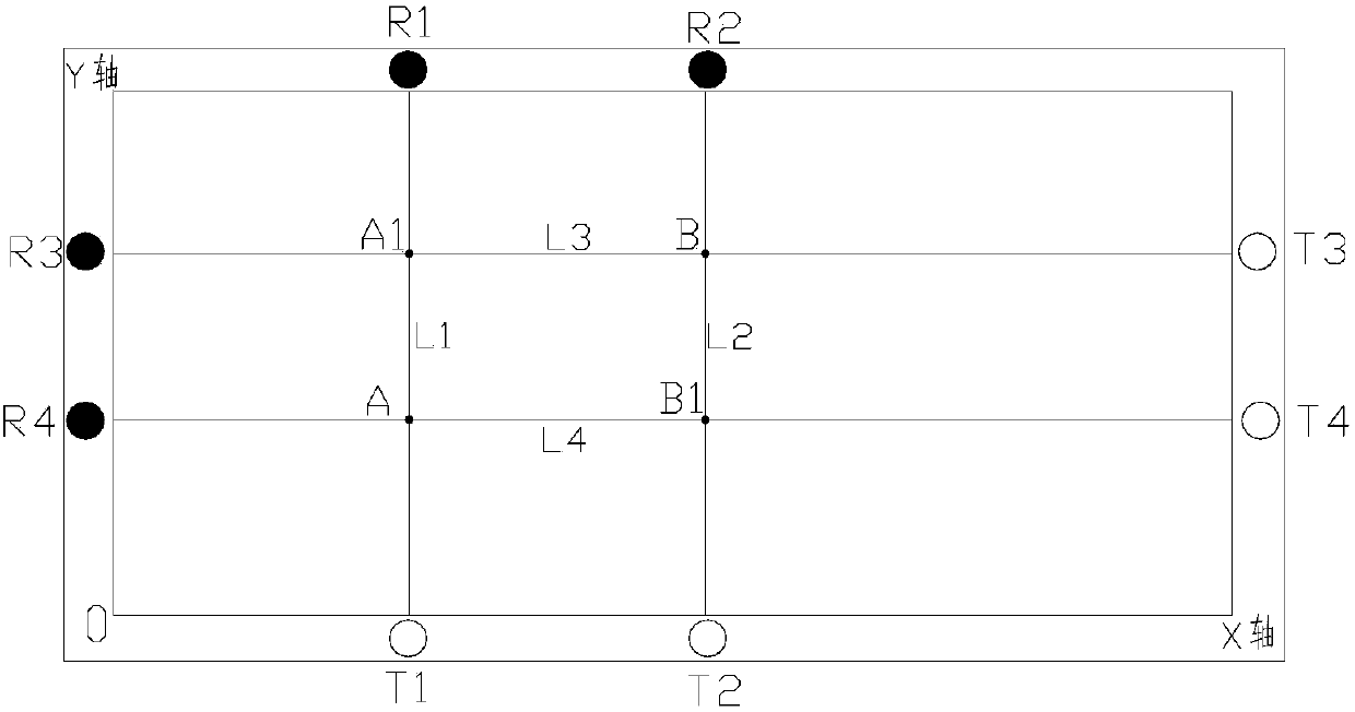
[0026] (2) Sequentially scan the infrared tubes on the screen in the X-axis and Y-axis directions of the Cartesian coordinate system (an infrared emitting tube corresponds to an infrared receiving tube, called an infrared pairing tube), according to the touch The occlusion signal of the point forms an orthogonal optical path (that is, a scanning optical path perpendicularly intersecting on the X axis and the Y axis), and the coordinates of the touch point are preliminarily confirmed by the intersection point of the orthogonal optical path.

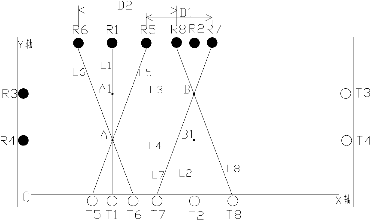
[0027] (3) Carry out two oblique-axis optical path scans w...


PUM


Abstract

The invention discloses a multi-point touch identification method for an infrared touch screen, which comprises the steps of determining a rectangular plane coordinate system by taking one corner of the touch screen as the origin of coordinates; scanning the infrared germinate transistors on the screen in the X axis and Y axis directions of the rectangular coordinate system, forming orthogonal light paths according to the shield signals of touch points, and primarily determining the touch point by the crossing point of the orthogonal light paths; performing oblique axis light path scanning in the X or Y axis, and calculating the linear distance between the lowering points, wherein crossing lines are formed by the oblique axis light path at the crossing point of the orthogonal light paths in the X or Y axis and the lowering points are formed by the crossing lines at an infrared receiving tube; and determining the position of the real touch point according to the crossing point of the orthogonal light paths and the linear distance between the lowering points. The multi-point touch identification method for the infrared touch screen has the advantages of accurately determining the real touch point by scanning the primarily determined point by an oblique axis light path scanning mode, and being fast in computing speed without causing errors due to the abnormity of a certain LED (light emitting diode) on the touch screen.

Description

technical field [0001] The invention relates to the technical field of touch screen identification, in particular to an infrared touch screen multi-touch identification method. Background technique [0002] The infrared touch screen uses a pair of infrared emitting tubes and infrared receiving tubes to detect whether there is an obstruction between the two tubes to identify the touch point. Currently, infrared touch screens get more logical touch points than actual touch points when performing multi-touch. A large part of these logical touch points are "false points", that is, the position is not actually touched, so these "false points" need to be removed to confirm the position of the real touch point. [0003] Generally, the existing multi-touch recognition method is: adopt infrared scanning to scan vertically and obliquely one by one. When scanning, one infrared emitting tube corresponds to one infrared receiving tube, and the corresponding infrared emitting tube and in...

Claims


Application Information

Patent Timeline
IPC IPC(8): G06F3/042
Inventor 莫少东周江洪
Owner 陈云波
Why Eureka
Try Eureka