On-chip multi-winding transformer

A multi-winding transformer and transformer technology, applied in the direction of transformer/inductor coil/winding/connection, etc., can solve the problems of occupation, large chip area, etc., and achieve the effect of reducing cost, reducing area, and good matching

Active Publication Date: 2013-10-30
REALTEK SEMICON CORP
View PDF4 Cites 14 Cited by
  • Summary
  • Abstract
  • Description
  • Claims
  • Application Information

AI Technical Summary

Problems solved by technology

However, passive components in integrated circuits, such as inductors or their transformers, often occupy a large chip area; therefore, how to simplify their number and minim

Method used


Image

  • On-chip multi-winding transformer
  • On-chip multi-winding transformer
  • On-chip multi-winding transformer

Examples


Embodiment Construction

[0053] The features, purpose, functions, and technical means used to achieve the present invention will be described and illustrated in detail below with reference to the accompanying drawings.

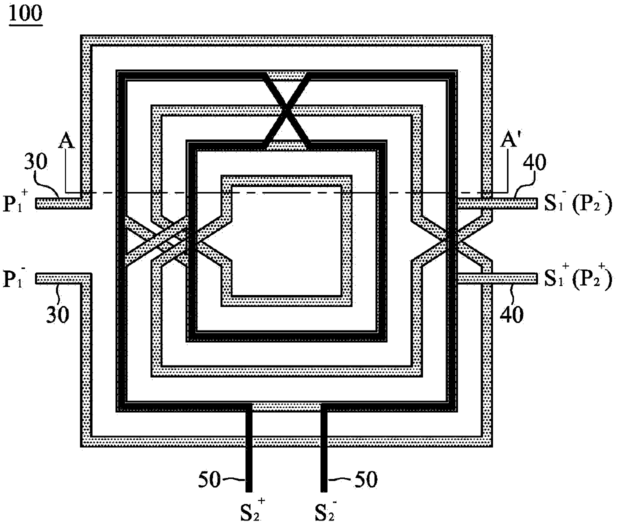
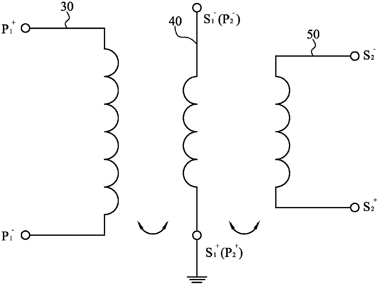
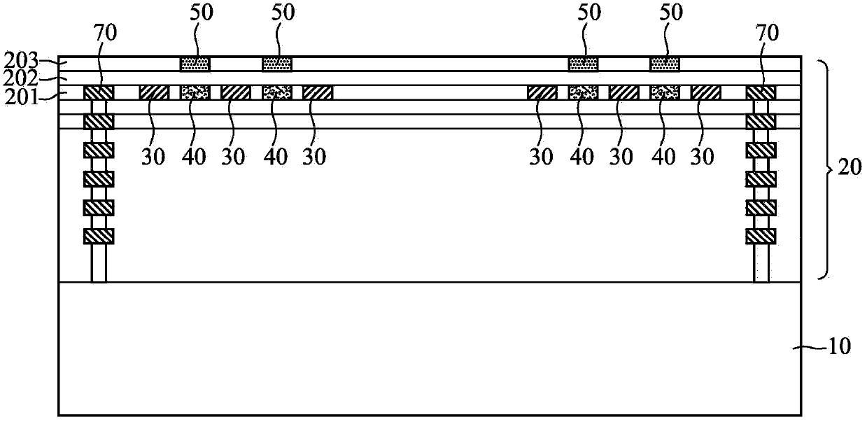
[0054] The disclosure of the present invention relates to an on-chip multi-winding transformer, which integrates the transformer in a multi-layer structure on a semiconductor substrate or chip by means of an integrated circuit process. According to the function or requirement of its application circuit, the transformer has at least three windings formed by conductive coils. For example, the first, second and third windings can be formed in the same layer or different layers of metal in the multilayer metal structure on the substrate, and the circuit patterns of the windings are spatially separated or independent from each other, which It can contain a single number or multiple coils, and realize the voltage conversion function of two or more transformers by utilizing the electromagnet...


PUM


Abstract

The invention discloses an on-chip multi-winding transformer which is formed on an integrated circuit board. The on-chip multi-winding transformer comprises a multi-winding structure and a protection ring. The multi-winding structure at least comprises a first winding, a second winding and a third winding which are mutually discrete in space. The protection ring is formed on the periphery of the multi-winding structure. The first winding and the second winding serve as a first transformer body, and the second winding and the third winding serve as a second transformer body. According to the on-chip multi-winding transformer, more than three windings (more than two transformer bodies) can be integrated as a single element, so that the area is reduced, the multi-winding transformer is well matched, and the cost is further reduced.

Description

technical field [0001] The present invention relates to an on-chip transformer, in particular to an on-chip multi-winding transformer with more than three windings. Background technique [0002] In the application field of wireless communication, the three main units of the system are transmitter, antenna, and receiver. Generally speaking, the wireless signals transmitted in the air are all single-ended signals, but the differential circuit inside the transmitter is a differential signal, so the transmitter must integrate its internal The differential signal is converted into a single-ended signal before it can be sent to the air through the antenna; on the other hand, the receiver must convert the single-ended signal received by the antenna into a differential signal before it can be transmitted It is used by a low noise amplifier (LNA) inside it. This type of signal conversion operation is realized by a balanced-to-unbalanced (balun) transformer, and each of the transmit...

Claims


Application Information

Patent Timeline
IPC IPC(8): H01F27/28
Inventor 黄凯易陈又新
Owner REALTEK SEMICON CORP
Why Eureka
Try Eureka