Natural gas desulfuration and liquid-removing device and desulfuration technology thereof

A technology of desulfurization device and desulfurization process, applied in the direction of gas fuel, petroleum industry, fuel, etc., can solve problems such as cost increase, liquid discharge pipeline blockage, safety accidents, etc., achieve improved effect, realize solid-liquid separation, and avoid U-shaped The effect of tube clogging

Active Publication Date: 2013-12-04
BEIJING SJ ENVIRONMENTAL PROTECTION & NEW MATERIAL CO LTD
View PDF6 Cites 5 Cited by
  • Summary
  • Abstract
  • Description
  • Claims
  • Application Information

AI Technical Summary

Problems solved by technology

[0008] The technical problem solved by the present invention is that in the prior art, when the gas-liquid separation is performed on natural gas before desulfurization, it is necessary to install an insulation layer on the waste liquid storage tank after gas-liquid separation, resulting in a substantial increase in cost. In addition, after gas-liquid separation The liquid contains solid impurities. If the liquid is directly discharged, it will also cause blockage of the liquid discharge pipeline, which is likely to cause a safety accident. In order to provide a method that does not need to provide an insulation layer for the waste liquid storage tank and automatically maintains the waste in the waste liquid storage tank. The liquid does not freeze, and can effectively deal with the method of solid impurities in the waste liquid after gas-liquid separation

Method used


Image

  • Natural gas desulfuration and liquid-removing device and desulfuration technology thereof
  • Natural gas desulfuration and liquid-removing device and desulfuration technology thereof
  • Natural gas desulfuration and liquid-removing device and desulfuration technology thereof

Examples


Embodiment 1

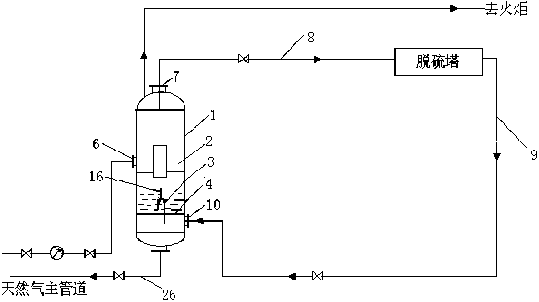
[0055] The natural gas deliquefaction and desulfurization device includes a gas-liquid separation tank 1, a gas-liquid separator 2 is arranged in the gas-liquid separation tank 1, and the gas-liquid separator 2 selects a cyclone separator, and the cyclone separator combines the The inner space of the gas-liquid separation tank 1 is divided into a gas collection chamber and a liquid collection chamber, the gas collection chamber is located at the top of the cyclone separator, and the liquid collection chamber is located at the bottom of the cyclone separator; The middle part of the liquid separation tank 1 is provided with a first natural gas inlet 6, and the first natural gas inlet 6 communicates with the cyclone separator; the top of the gas-liquid separation tank 1 is provided with a first natural gas outlet 7. The bottom of the liquid separation tank 1 is provided with a liquid outlet; the natural gas deliquification and desulfurization device also includes a desulfurization...

Embodiment 2

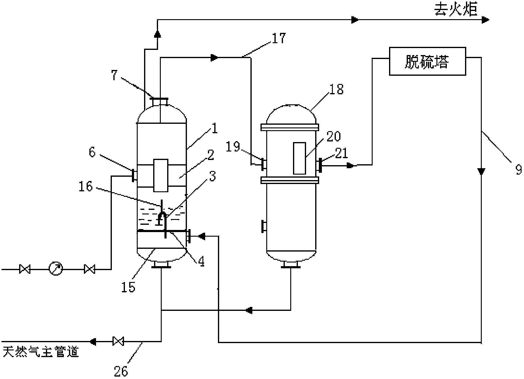
[0058] The natural gas deliquefaction and desulfurization device described in this embodiment, on the basis of Embodiment 1, selects the cyclone gas-liquid separator as the gas-liquid separator in this embodiment, between the cyclone gas-liquid separator and the desulfurization tower A coalescing tank 18 is also arranged between them, and the first natural gas outlet 7 of the gas-liquid separation tank 1 is connected to the natural gas inlet 19 provided on the side wall of the coalescing tank 18 through a pipeline 17, and the natural gas inlet 19 is connected to the The coalescing inner core 20 provided in the coalescing tank 18 is connected; the side wall of the coalescing tank 18 is provided with a natural gas outlet 21, and the natural gas outlet 21 is connected with the gas inlet of the desulfurization equipment; the coalescing A liquid outlet is provided at the bottom of the tank 18 .

[0059] In this embodiment, when the natural gas deliquefaction and desulfurization dev...

Embodiment 3

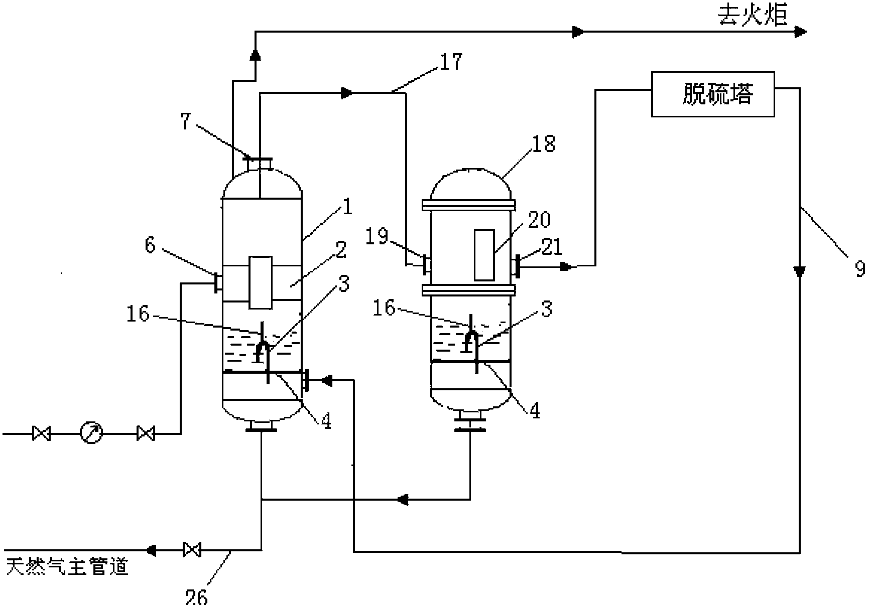
[0061] The natural gas deliquefaction and desulfurization device described in this embodiment, on the basis of Embodiment 2, is provided with a liquid collecting plate 4 at the lower part of the coalescing tank 18, and the liquid collecting plate 4 divides the lower part of the coalescing tank 18 into an upper part Liquid collection chamber and lower liquid discharge chamber; an inverted U-shaped tube 3 with an inner diameter of 6mm is arranged in the liquid collection chamber, and one end of the inverted U-shaped tube 3 is placed above the liquid collection plate 4, and is located in the liquid collection chamber. Below the liquid surface in the cavity, the other end extends through the liquid collecting plate 4 into the discharge cavity; the middle part of the top of the inverted U-shaped tube 3 is also provided with a vertical pipeline 16 communicating with the inside of the U-shaped tube, so The inner diameter of the vertical pipeline 16 is 6mm, and the top of the vertical ...


PUM


Abstract

The invention provides a natural gas desulfuration and liquid-removing device and a desulfuration technology thereof, and belongs to the technology field of chemical engineering. The natural gas desulfuration and liquid-removing device comprises a natural transportation pipeline, a gas-liquid separation tank, and a desulfuration device. The bottom of the gas-liquid separation tank is provided with a liquid collecting plate and an inverted U-shaped pipe, the separated liquid from the gas-liquid separation tank slowly drops into a lower cavity, which is arranged below the liquid collecting plate, through the inverted U-shaped pipe, then desulfurated natural gas in induced into the lower cavity, which is arranged below the gas-liquid separation tank, the liquid in the cavity is atomized through a huge flow of natural gas, and then the atomized liquid is brought back to the natural gas main pipeline with the desulfurated natural gas. The natural desulfuration and liquid-removing device and the desulfuration technology thereof have the advantages of low cost of desulfuration device, environment-friendly desulfuration technology, and resource saving.

Description

technical field [0001] The invention relates to a natural gas deliquification and desulfurization device and a desulfurization process thereof, which belong to the technical field of chemical industry. Background technique [0002] Natural gas contains hydrogen sulfide, mercaptans, heavy hydrocarbon gas, saturated water and other impurities. Hydrogen sulfide in natural gas meets water to form weak acid. The existence of weak acid will cause corrosion of steel and other equipment and pipelines. In addition, if the natural gas containing hydrogen sulfide is used as civil fuel, the exhaust gas generated after the combustion of natural gas will contain sulfide, and the sulfide will also pollute the environment and endanger human health. Therefore, it is first necessary to remove the hydrogen sulfide in the extracted natural gas to meet the requirements of factory production and commercial gas use. [0003] At present, the desulfurization methods used in domestic natural gas mai...

Claims


Application Information

Patent Timeline
Patent Type & Authority Applications(China)
IPC IPC(8): C10L3/10
Inventor 林科李廷均肖青
Owner BEIJING SJ ENVIRONMENTAL PROTECTION & NEW MATERIAL CO LTD
Why Eureka
Try Eureka