Profile steel rolling production line and production method thereof

A production line and section steel technology, applied in metal rolling and other directions, can solve the problems of increasing the length of the conveyor roller table, construction investment, construction engineering quantity workshop production energy consumption and production cost, so as to reduce the equipment failure rate and improve the roller Rotation flexibility and the effect of reducing engineering construction investment

Active Publication Date: 2013-12-11
CISDI ENG CO LTD
View PDF8 Cites 4 Cited by
  • Summary
  • Abstract
  • Description
  • Claims
  • Application Information

AI Technical Summary

Problems solved by technology

Since the process of rolling and producing section steel products has many deformation passes, the rolled piece needs to be rolled in multiple passes (roll grooves) of the roll. In order to meet the production needs of each stand rolling mill for section steel production, the strip What comes is the increase in the number of rolling mills and the increase in the length of the conveyor roller table, which will inevitably lead to an increase in construction investment, construction engineering volume, workshop production energy consumption and production costs

Method used


Image

  • Profile steel rolling production line and production method thereof
  • Profile steel rolling production line and production method thereof
  • Profile steel rolling production line and production method thereof

Examples


Embodiment 1

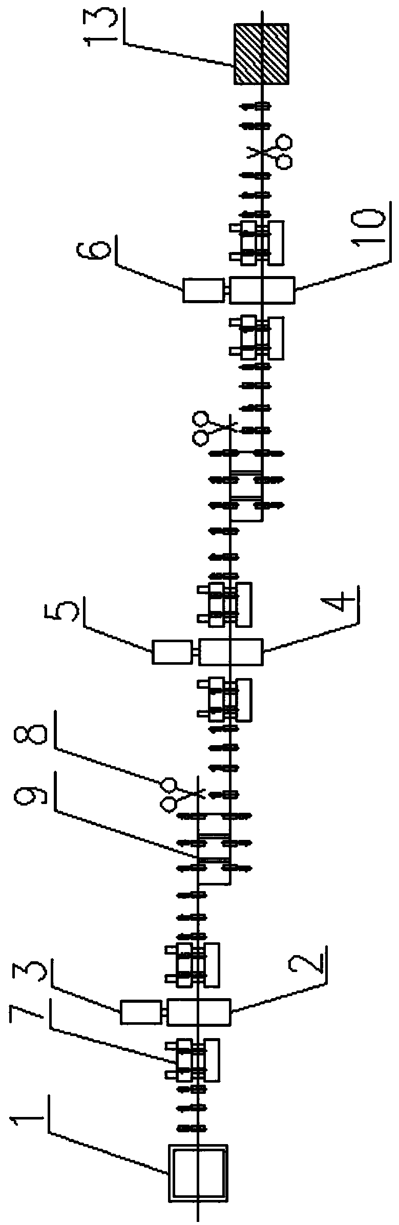
[0025] figure 1 It is the process equipment layout diagram of embodiment 1 of the present invention, as figure 1 As shown, the section steel rolling production line of the present invention comprises a heating unit 1, a rough rolling unit, an intermediate rolling unit, a finish rolling unit and a finishing unit 13 arranged in sequence, and the rough rolling unit includes a rough rolling mill 2 and a rough There are the same number of driving devices I3 in the rolling mill 2, the driving device I3 drives the roughing mill 2 to move axially along the rolls of the roughing mill, and the rolls of the roughing mill 2 are sequentially provided with more than two rolling grooves with different slot holes along the axial direction; The intermediate rolling unit includes one intermediate rolling mill 4 and the same number of driving devices II5 as the intermediate rolling mill 4, the driving device II5 drives the intermediate rolling mill 4 to move axially along the intermediate rollin...

Embodiment 2

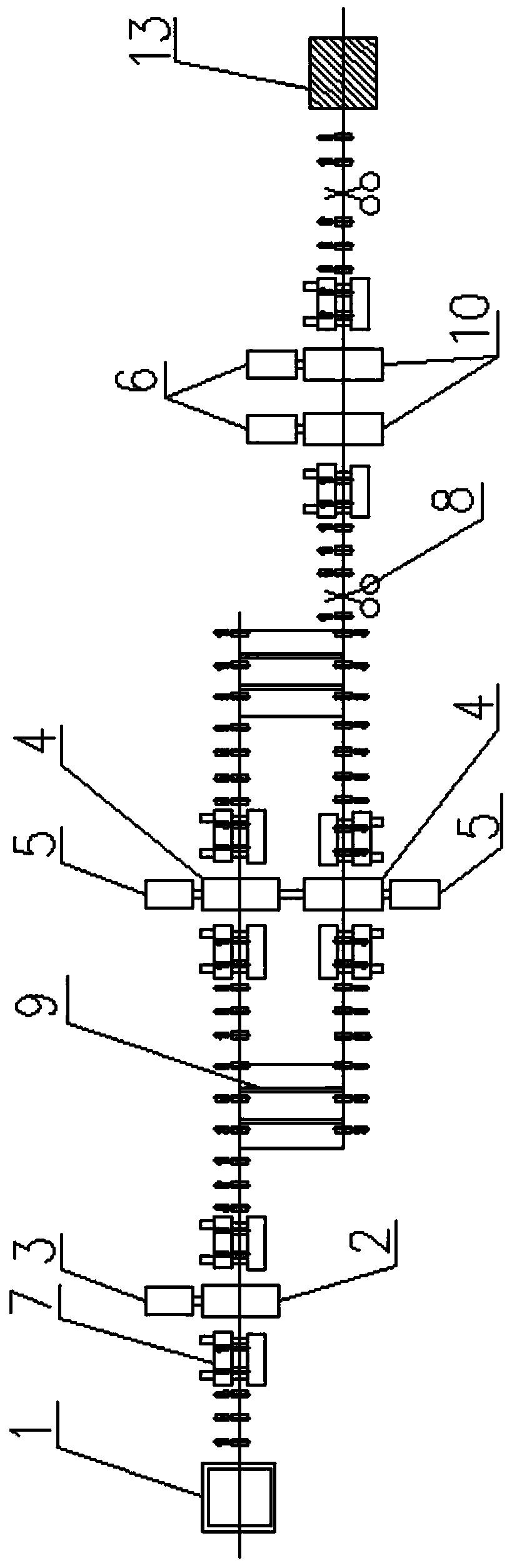
[0030] figure 2 It is the process equipment layout diagram of embodiment 2 of the present invention, as figure 2 As shown, the section steel rolling production line of the present invention comprises a heating unit 1, a rough rolling unit, an intermediate rolling unit, a finish rolling unit and a finishing unit 13 arranged in sequence, and the rough rolling unit includes a rough rolling mill 2 and a rough There are the same number of driving devices I3 in the rolling mill 2, the driving device I3 drives the roughing mill 2 to move axially along the rolls of the roughing mill, and the rolls of the roughing mill 2 are sequentially provided with more than two rolling grooves with different slot holes along the axial direction; The intermediate rolling unit includes two intermediate rolling mills 4 and the same number of driving devices II5 as the intermediate rolling mills 4. The driving device II5 drives the intermediate rolling mills 4 to move axially along the intermediate r...

Embodiment 3

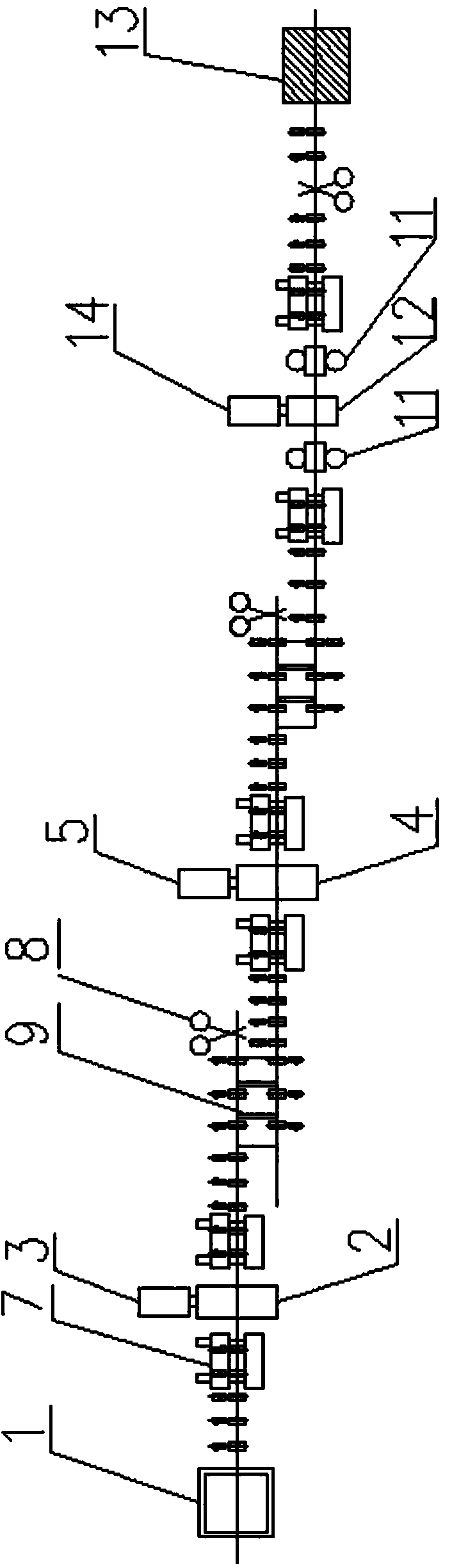
[0035] image 3 It is the process equipment layout diagram of embodiment 3 of the present invention, as image 3As shown, the section steel rolling production line of the present invention comprises a heating unit 1, a rough rolling unit, an intermediate rolling unit, a finish rolling unit and a finishing unit 13 arranged in sequence, and the rough rolling unit includes a rough rolling mill 2 and a rough There are the same number of driving devices I3 in the rolling mill 2, the driving device I3 drives the roughing mill 2 to move axially along the rolls of the roughing mill, and the rolls of the roughing mill 2 are sequentially provided with more than two rolling grooves with different slot holes along the axial direction; The intermediate rolling unit includes one intermediate rolling mill 4 and the same number of driving devices II5 as the intermediate rolling mill 4, the driving device II5 drives the intermediate rolling mill 4 to move axially along the intermediate rolling...


PUM


Abstract

The invention relates to a profile steel rolling production line and a production method thereof. The profile steel rolling production line comprises a heating unit, a rough rolling unit, a medium rolling unit, a fine rolling unit and a finishing unit, wherein each of the rough rolling unit and the medium rolling unit comprises a rolling mill and a driving device for driving the rolling mill to move along the axial direction of a rolling roller; the rolling rollers of the rolling mills are provided with rolling grooves with different groove holes; the fine rolling unit comprises a two-roller rolling mill or the fine rolling unit comprises a four-roller universal rolling mill, a two-roller edging mill and a four-roller universal rolling mill which are arranged in sequence; the two-roller rolling mill and the two-roller edging mill are provided with driving devices which move along the axial direction of rolling rollers I; the rolling rollers I are further provided with rolling grooves I with different groove holes. After a rolling piece is heated and is sequentially rolled by the upper and lower different rolling grooves through the corresponding rolling rollers on the rough rolling unit, the rolling piece enters the medium rolling unit to be sequentially rolled by the upper and lower different rolling grooves through the corresponding rolling rollers; finally, the rolling piece enters the fine rolling unit to be rolled to form a finished-product sectional material. According to the profile steel rolling production line and the production method thereof, the quantity of the rolling mills is reduced, the weight of a conveying roller bed is reduced, the production line is simplified and the production efficiency is improved.

Description

technical field [0001] The invention relates to the field of iron and steel metallurgy, in particular to a section steel rolling production line and a production method thereof. Background technique [0002] Sectional steel is a long strip of steel with a certain cross-sectional shape, including hot rolling, cold bending, welding, extrusion and other production methods. It is also divided into simple section, complex section and periodic section, among which the rolling method occupies an absolute position. Usually, the method of rolling and producing section steel is: sending the billet heated to high temperature into the roll with multiple passes to deform the rolled piece for multiple passes to obtain the finished section product in the hot state, after cooling and finishing The final product is obtained after the process. Since the process of rolling and producing section steel products has many deformation passes, the rolled piece needs to be rolled in multiple passes...

Claims


Application Information

Patent Timeline
Patent Type & Authority Applications(China)
IPC IPC(8): B21B1/08
Inventor 谭成楠曹勇闵建军周民
Owner CISDI ENG CO LTD
Why Eureka
Try Eureka