
Damping and noise reduction device of fan
A fan and noise reduction technology, which is applied in the field of shock absorption and noise reduction, can solve the problems of undiscovered axial flow fans, and achieve the effects of simple structure, reduced impact and extended service life.
- Summary
- Abstract
- Description
- Claims
- Application Information
AI Technical Summary
Problems solved by technology
Method used
Image

Examples
Embodiment Construction
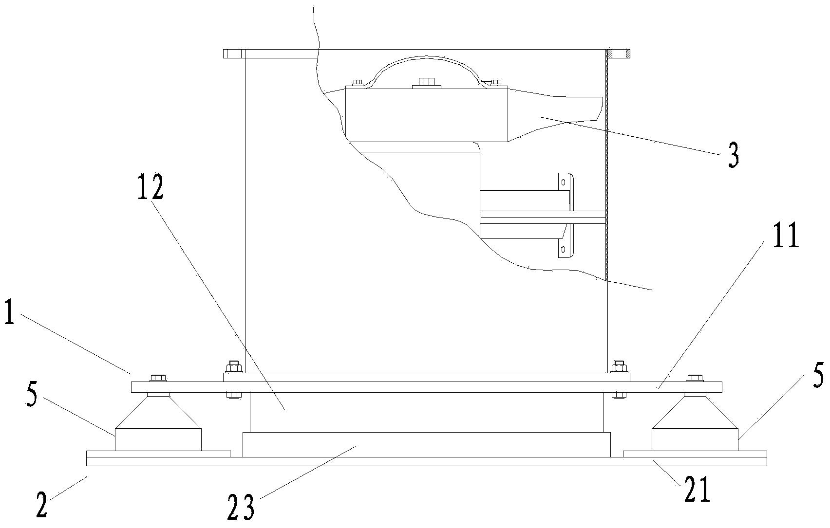
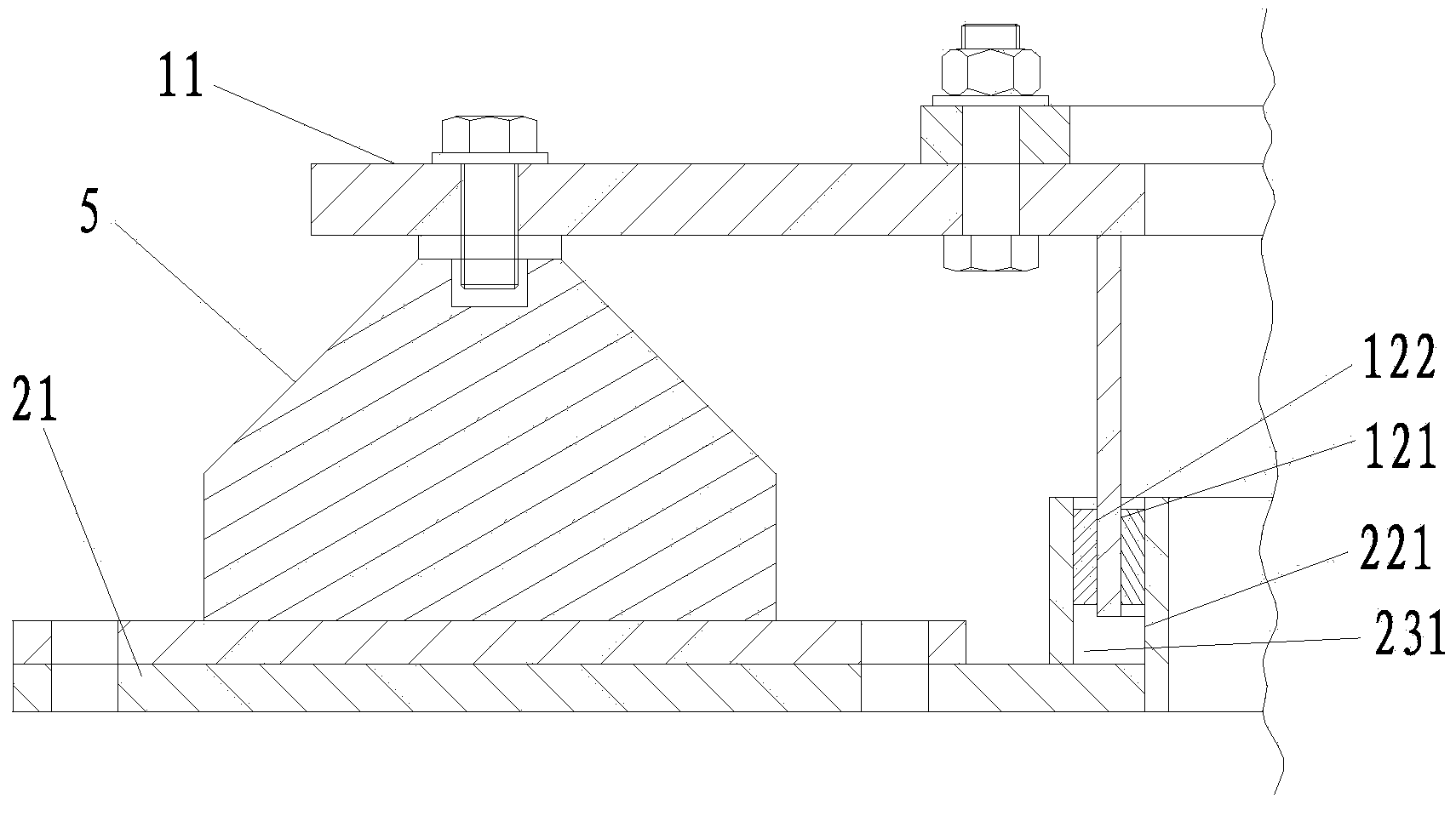
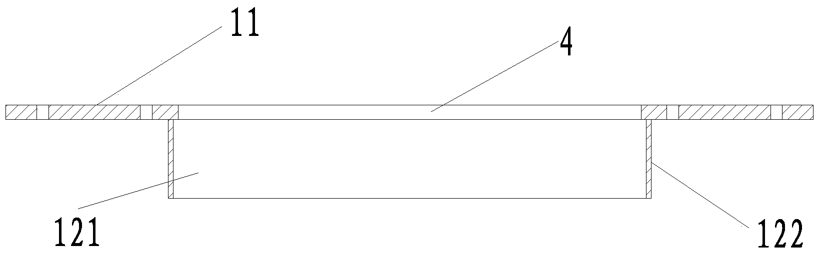
[0028] like figure 1 , figure 2 , image 3 , Figure 4 , Figure 5 , Image 6 and Figure 7 As shown, a fan shock and noise reduction device, it includes a fixed seat 1 for installing a fixed fan and a base 2 located below the fixed seat and fixed to the hull. The fixed seat includes an upper pressing plate 11 and is arranged on the upper pressing plate The lower first cylinder 12 , the base includes a lower pressing plate 21 and a second cylinder 22 and a third cylinder 23 disposed above the lower pressing plate 21 . The blower fan 3 is fixed on the upper middle part of the upper pressing plate 11 . Ventilation holes 4 for the air driven by the fan 3 to flow in or out are respectively opened on the upper pressing plate 11 at the middle part of the first cylinder 12 and the lower pressing plate 21 at the middle part 22 of the second cylinder.
[0029] The first cylindrical body 12 , the second cylindrical body 22 and the third cylindrical body 23 are respectively fixed...
PUM
 Abstract
Description
Claims
Application Information