Fall plate assembly for warp knitting machine

A technology of pressing plate and warp knitting machine, which is applied in the directions of flat warp knitting machine, warp knitting, textile and paper making, etc., can solve problems such as large space, and achieve the effect of widening the possibility of jacquard

Active Publication Date: 2014-01-15
KARL MAYER STOLL R&D GMBH
View PDF13 Cites 2 Cited by
  • Summary
  • Abstract
  • Description
  • Claims
  • Application Information

AI Technical Summary

Problems solved by technology

Correspondingly, relatively large spaces are r

Method used


Image

  • Fall plate assembly for warp knitting machine

Examples


Embodiment Construction

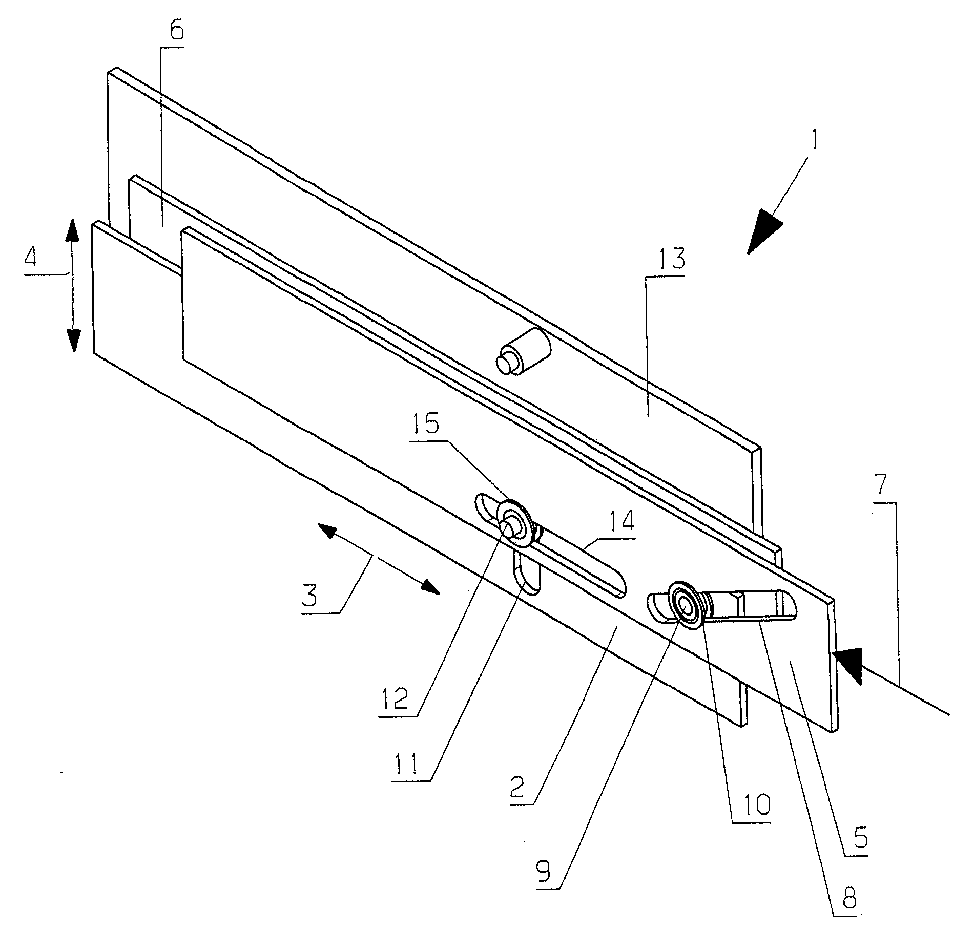
[0027] The yarn pressing plate assembly 1 shown only schematically in this figure has a yarn pressing plate 2 which extends parallel to the displacement direction 3 indicated by the double arrow.

[0028] In warp knitting machines, this direction is defined as the displacement direction 3 in which the knitting elements are arranged side by side at the crosspieces in rows. The direction of displacement corresponds at least approximately to the width direction of the warp knitting machine. During mesh formation, the guide needles are moved relative to the needles in the direction of displacement, thereafter through the gaps between the needles, and thereafter again in the direction of displacement opposite to the first movement in the direction of displacement Finally, it passes through the gap between the knitting needles.

[0029] When terms such as "parallel" or "vertical" are mentioned in this description, these terms are then not to be understood in a strictly mathematical...


PUM


Abstract

The invention relates to a fall plate assembly (1) for a warp knitting machine. The fall plate assembly (1) is provided with a fall plate (2) extending in parallel to a shifting direction (3); and a fall plate driver (7) driving the fall plate (2) in a moving direction (4) which is perpendicular to the shifting direction (3). The invention aims to make it possible that the fall plate can be driven without relatively large consumption and the working speed can be relatively high. Therefore, the fall plate driver (7) is configured to have a drive element (5) which can move in the shifting direction and act on the fall plate through steering assemblies (8-10).

Description

technical field [0001] The invention relates to a pressure plate assembly of a warp knitting machine with a pressure plate extending parallel to the displacement direction (Versatzrichtung) and a pressure plate drive for driving the pressure plate in a direction of movement perpendicular to the displacement direction . Background technique [0002] In short, the knitting needles and guide needles (Legenadels) work together in the warp knitting machine to form the mesh (Maschen) of the knitted fabric (Wirkware). In this case, the knitting needles are usually arranged in rows on a needle bed. The yarn guide needles can be arranged at a plurality of yarn guide needle beds. Each bar then carries rows of guide needles. For mesh formation, the guide needles have to be moved relative to the knitting needles in a direction parallel to the row in which the guide needles are arranged. This direction is also referred to as "shift direction". In a further movement phase, the guide ...

Claims


Application Information

Patent Timeline
IPC IPC(8): D04B27/00D04B27/24
CPCD04B27/08D04B23/22
Inventor G.克劳斯
Owner KARL MAYER STOLL R&D GMBH
Why Eureka
Try Eureka