Projection device and method for projection and imaging thereof

A projection device and projection technology, applied in the field of projection, can solve the problems of increasing the power consumption of extra cameras, increasing the size of the equipment, and high cost, and achieving the effects of good projection effect, small size and low cost

Active Publication Date: 2015-11-25
HUAWEI DEVICE CO LTD
View PDF5 Cites 0 Cited by
  • Summary
  • Abstract
  • Description
  • Claims
  • Application Information

AI Technical Summary

Problems solved by technology

However, this consumes a lot of power, which requires additional power consumption of the camera, and the size of the device increases and the cost is high.

Method used


Image

  • Projection device and method for projection and imaging thereof
  • Projection device and method for projection and imaging thereof
  • Projection device and method for projection and imaging thereof

Examples


Embodiment 1

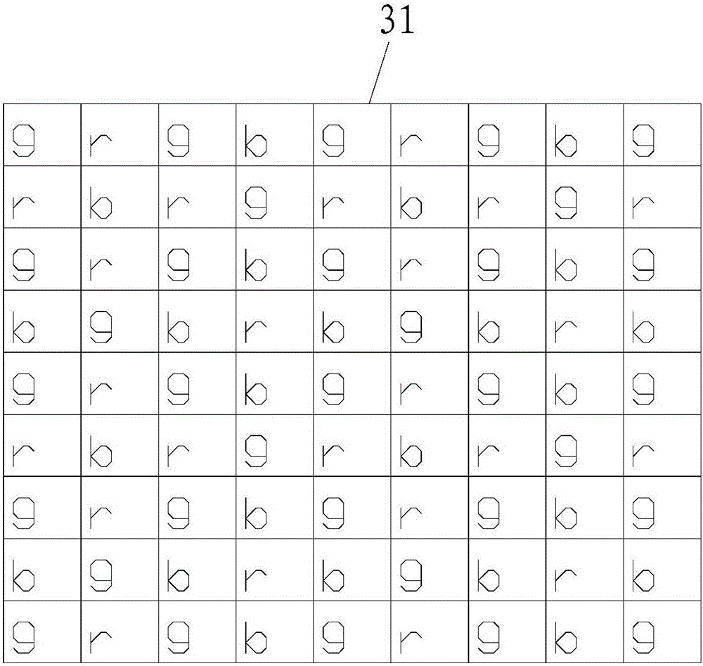
[0060] like figure 1 and figure 2 As shown, a projection device provided by an embodiment of the present invention includes a first light modulation component (not marked in the figure) for modulating the projection light source 91, and is used for modulating the light formed by the first light modulation component into projection A light projection panel 3 and a second light modulation component (not marked in the figure) for projecting projection light onto the projection surface.

[0061] The projection device also has an imaging component for imaging the projection surface 92, and the reflected light of the projection surface 92 reaches the imaging component (not marked) from the second light modulation component or the second light modulation component and the first light modulation component. The imaging component is disposed on the projection panel 3 or is disposed independently of the projection panel 3 .

[0062] The imaging component can share some or all parts of...

Embodiment 2

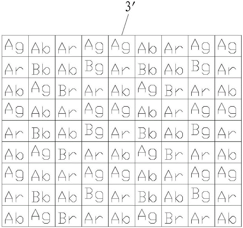
[0091] Different from the three-piece LCoS projection panel in the embodiment, the projection panel 3' in this embodiment is a single-piece LCoS projection panel, which includes a red projection unit, a green projection unit and a blue projection unit; Monolithic LCoS projection panel 3'. The imaging component includes a red photosensitive unit, a green photosensitive unit and a blue photosensitive unit; a red projection unit, a green projection unit, a blue projection unit, a red photosensitive unit, a green photosensitive unit and a blue photosensitive unit are arranged in a matrix. In this embodiment, the projection unit is represented by A, the photosensitive unit is represented by B, the red is represented by r, the green is represented by g, and the blue is represented by b. Therefore: the red projection unit is represented by Ar, the green projection unit is represented by Ag, the blue projection unit is represented by Ab, the red photosensitive unit is represented by B...

Embodiment 3

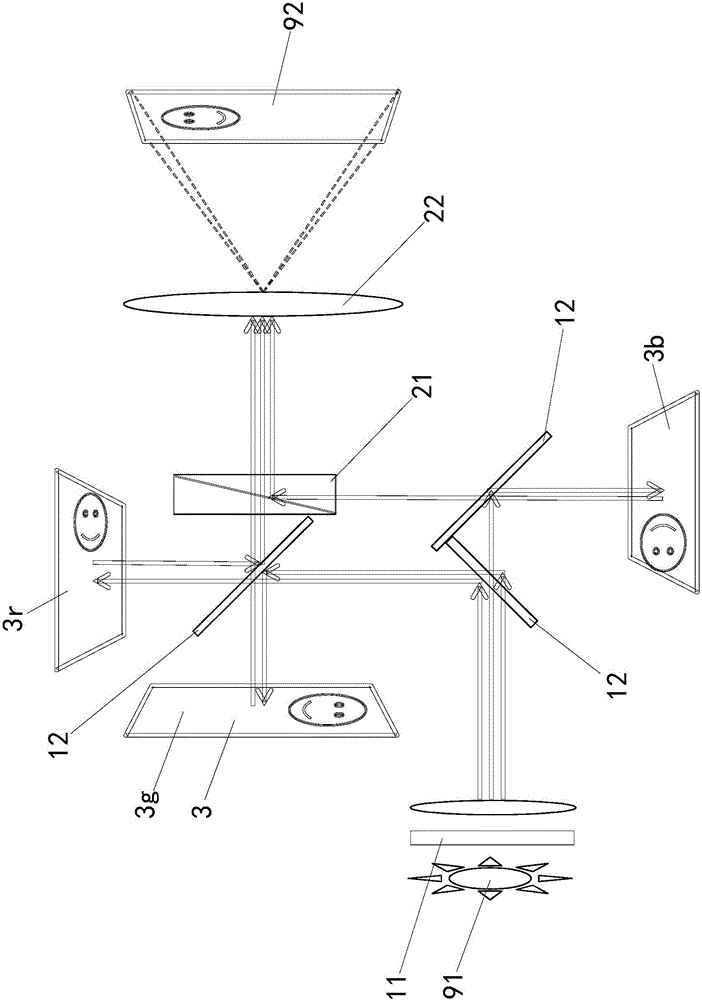
[0098] Different from the imaging components integrated in the projection panel in Embodiments 1 and 2, in the projection device in this embodiment, the imaging components are set separately from the projection panel 3 ″. The imaging components and the projection panel 3 ″ are set separately, and the imaging components include a photosensitive panel 41 , the light on the projection surface 92 reaches the photosensitive panel 41 from the second light modulation component. The imaging part also includes a polarizer 42, the polarizer 42 is perpendicular to the polarizer (the polarizer 12 in the first light modulation part) used for the projection panel 3", the polarizer 42 refracts or / and The reflected ambient light is projected onto the photosensitive panel 41 .

[0099] For a projection device with a three-piece projection panel with a 3" structure, the optical path is as follows Figure 17 shown. The projection light emitted by the projection light source 91 is processed by ...


PUM


Abstract

The invention belongs to the technical field of projection, and discloses a projection device as well as a projection and camera shooting method thereof. The projection device comprises a first light modulation part, a projection panel, a second light modulation part and an imaging part, wherein reflected light of a projective plane reaches the imaging part through the second light modulation part or through the second light modulation part and the first light modulation part; and the imaging part is arranged on the projection panel or arranged independent of the projection panel. The projection and camera shooting method comprises steps as follows: a projection light source reaches the projection panel through the first light modulation part; the projection panel projects the projection light to the projection plane through the second light modulation part; the light of the projective plane reaches the imaging part through the second light modulation part or through the second light modulation part and the first light modulation part; and imaging data of the imaging part for the projection plane is read. The projection device as well as the projection and camera shooting method thereof has the advantages of good projection effect, small power consumption, small equipment size and low cost.

Description

technical field [0001] The invention belongs to the field of projection technology, and in particular relates to a projection device and projection and imaging methods thereof. Background technique [0002] Current projectors, such as LCoS (LiquidCrystalonSilicon, that is, liquid crystal attached to silicon, also known as liquid crystal on silicon, is a matrix liquid crystal display device based on reflection mode and very small in size) projectors, which use liquid crystal arrays to control the reflection of light. A device to achieve projection imaging. [0003] The LCoS projector in the prior art cannot automatically focus without other devices, and when projected onto a non-pure color background, the image will be affected by the projected background, resulting in poor projection effect. [0004] In the prior art, there is also a way to automatically adjust the focus of the projector by adding a camera near the projector and calculating the contrast of the projection im...

Claims


Application Information

Patent Timeline
Patent Type & Authority Patents(China)
IPC IPC(8): G03B21/14G03B21/20G02B27/28G02B27/10H04N9/31
Inventor 郭泽金何峰
Owner HUAWEI DEVICE CO LTD
Why Eureka
Try Eureka