Camera module and electronic equipment

A technology for camera modules and components, applied in televisions, electrical components, color TVs, etc., can solve problems such as the increase in the external dimensions of the drive motor, the increase in the overall size of the camera module, and the unfavorable miniaturization design of the camera module. Reduced overall size, miniaturized design, and improved response speed

Pending Publication Date: 2022-03-29
NANCHANG OFILM HUAGUANG TECH CO LTD
View PDF7 Cites 0 Cited by
  • Summary
  • Abstract
  • Description
  • Claims
  • Application Information

AI Technical Summary

Problems solved by technology

As the pixel level of the photosensitive chip increases, the overall size of the chip increases. Simultaneously, the size and weight of the lens also increase. The requirements for the load-bearing and driving force of the drive motor are getting higher and higher. The load-bearing performance is getting higher and higher, and the driving force is getting bigger and bigger, which leads to an increase in the overall size of the drive motor, which leads to an increase in the overall size of the camera module, which is not conducive to the miniaturization design of the camera module

Method used


Image

  • Camera module and electronic equipment
  • Camera module and electronic equipment
  • Camera module and electronic equipment

Examples


Embodiment Construction

[0055] The following will clearly and completely describe the technical solutions in the embodiments of the present invention with reference to the accompanying drawings in the embodiments of the present invention. Obviously, the described embodiments are only some of the embodiments of the present invention, not all of them. Based on the embodiments of the present invention, all other embodiments obtained by persons of ordinary skill in the art without making creative efforts belong to the protection scope of the present invention.

[0056] In the present invention, the terms "upper", "lower", "left", "right", "front", "rear", "top", "bottom", "inner", "outer", "middle", The orientations or positional relationships indicated by "vertical", "horizontal", "horizontal", and "longitudinal" are based on the orientations or positional relationships shown in the drawings. These terms are mainly used to better describe the present invention and its embodiments, and are not intended t...


PUM


Abstract

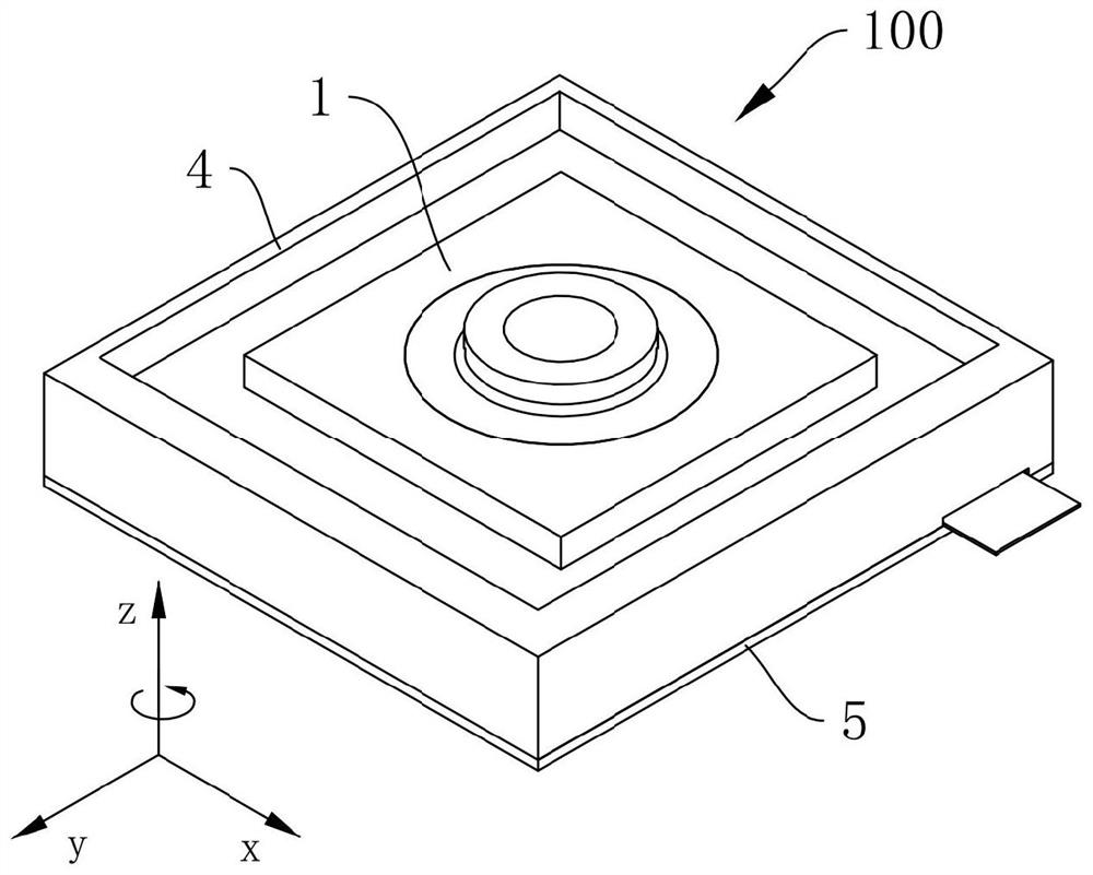
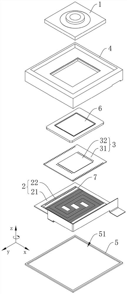
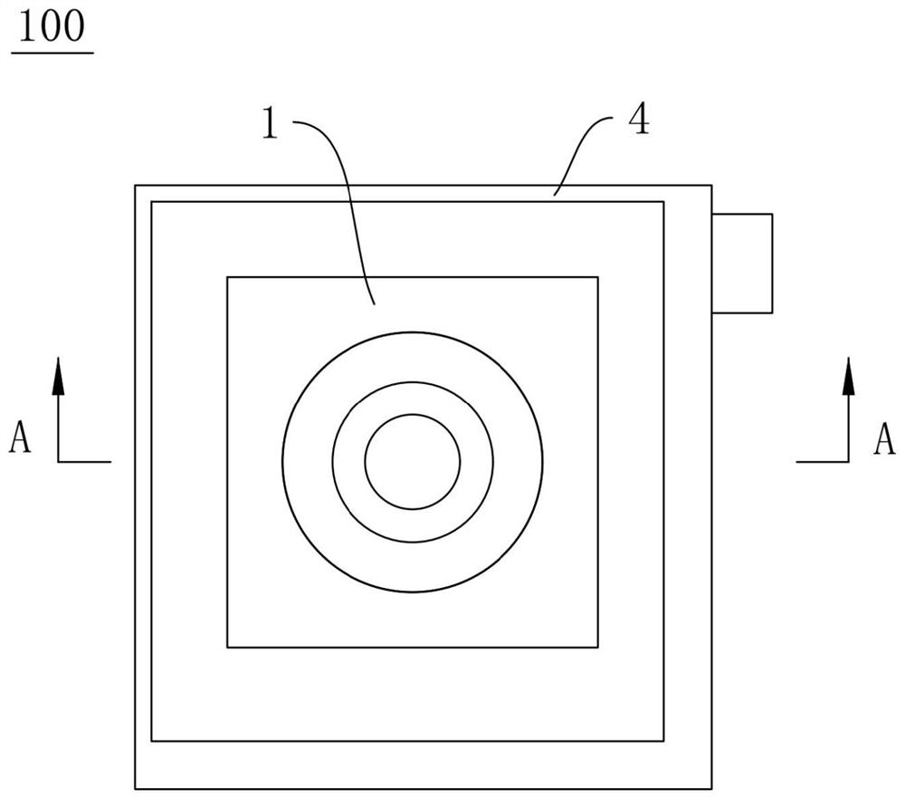
According to the camera module and the electronic equipment, the camera module comprises a lens assembly, an elastic supporting structure, a chip assembly and a power assembly, the chip assembly is arranged on a movable plate of the elastic supporting structure, and the power assembly comprises a first support, a connecting support, a first elastic component and a first power component. The first support is connected to a bearing plate of the elastic supporting structure, the connecting support is connected to the chip assembly, the two ends of the first elastic component are connected to the first support and the connecting support respectively, and the first elastic component bends and extends in the first direction. The first direction is the direction from the joint of the first elastic component and the first support to the joint of the first elastic component and the connecting support, and the first power component is connected to the first support and the connecting support and used for enabling the chip assembly to move in the optical axis direction for automatic focusing. By adopting the embodiment of the invention, the resistance borne by the chip assembly when the chip assembly moves along the optical axis direction can be reduced while the miniaturization design of the camera module is realized, and the response speed of automatic focusing is improved.

Description

technical field [0001] The invention relates to the technical field of imaging devices, in particular to a camera module and electronic equipment. Background technique [0002] Electronic devices such as cameras, smart phones, and smart watches in related technologies are often equipped with camera modules. In order to improve the shooting quality during shooting, most of the camera modules will include driving motors to drive the lens to move automatically. Focus to improve the shooting quality of the camera module. As the pixel level of the photosensitive chip increases, the overall size of the chip increases. Simultaneously, the size and weight of the lens also increase. The requirements for the load-bearing and driving force of the drive motor are getting higher and higher. The load-bearing performance of the camera is getting higher and higher, and the driving force is getting bigger and bigger, which leads to an increase in the overall size of the drive motor, which l...

Claims


Application Information

Patent Timeline
Patent Type & Authority Applications(China)
IPC IPC(8): H04N5/225H04N5/232
CPCH04N23/00H04N23/67
Inventor 马忠科陈小凤
Owner NANCHANG OFILM HUAGUANG TECH CO LTD
Why Eureka
Try Eureka