Artificial surface plasmon-based miniaturized low-pass filter

An artificial surface plasmon, low-pass filter technology, applied in the field of filters, can solve the problem that the wave vector transmission conversion efficiency cannot meet the ideal requirements, and achieves the effect of strong innovation, good technical foresight, and convenient processing.

Inactive Publication Date: 2016-06-22
NANJING UNIV OF AERONAUTICS & ASTRONAUTICS
View PDF4 Cites 9 Cited by
  • Summary
  • Abstract
  • Description
  • Claims
  • Application Information

AI Technical Summary

Problems solved by technology

However, the mismatch of the wave vector leads to the failure of the transmission conversion efficiency to meet the ideal requirements.

Method used


Image

  • Artificial surface plasmon-based miniaturized low-pass filter
  • Artificial surface plasmon-based miniaturized low-pass filter
  • Artificial surface plasmon-based miniaturized low-pass filter

Examples


Embodiment 1

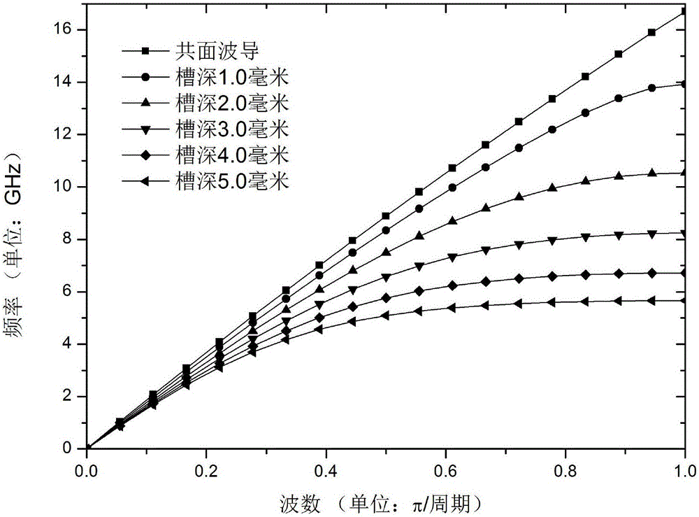
[0028] Such as image 3 As shown, the structure of the present invention is based on the coplanar waveguide, and its two metal grounding strips are etched with a rectangular structure slot unit array periodically distributed along the coplanar waveguide length direction (x direction), and the slot unit array is about the coplanar waveguide The width direction (y direction) is left-right symmetrical, and the two slot unit arrays are vertically symmetrical with respect to the central conductor strip. The depth of the slot unit (that is, the height in the y direction) increases uniformly from both sides to the middle in the x direction to form a pattern matching section, and the depth of the slot unit in the middle remains unchanged to form the SSPPs transmission section, and the number of slot units with gradually changing depths on both sides and the depth in the middle remain unchanged The number of slot units is set according to the transmission requirements of the guided wav...

Embodiment 2

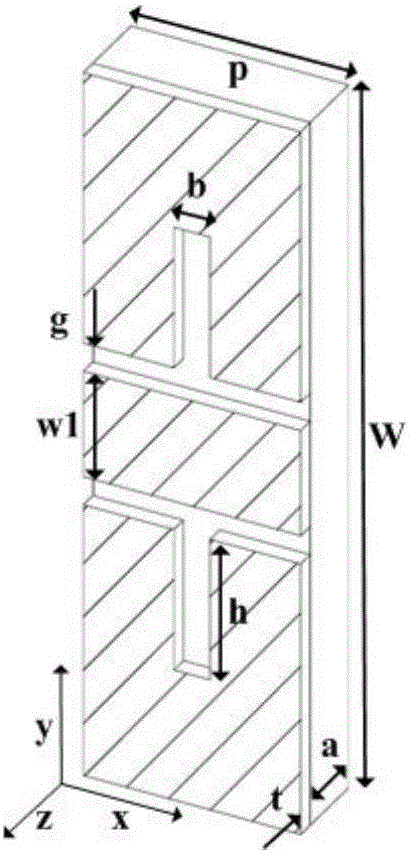
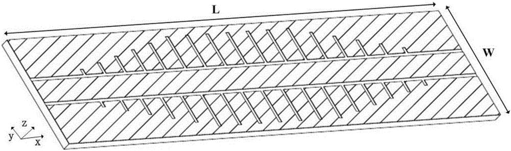
[0034] Such as Figure 6 As shown, it is consistent with the basic structure of Embodiment 1, the difference is that the groove unit of this embodiment adopts a T-shaped structure, the length of the overall structure is L=100mm, the width is W=20mm, the thickness of the dielectric substrate a=1.0mm, and the thickness of the metal layer t = 0.018mm.

[0035] Such as Figure 7As shown, the coplanar waveguide signal line width w1=3mm, and the distance between the signal line and the ground g=0.8mm is used to construct the port impedance of 50ohm. In this embodiment, the width of the transverse branch and the vertical branch of the T-shaped slot unit is equal to b=0.5mm, and the width of the transverse branch and the vertical branch can also be unequal. It is set according to the transmission requirements of the guided wave signal, and the period along the x direction is p= 4mm distribution. The length of the branches of the T-shaped groove unit in the x direction remains const...


PUM


Abstract

The invention discloses an artificial surface plasmon-based miniaturized low-pass filter. The artificial surface plasmon-based miniaturized low-pass filter is characterized by mainly comprising a coplanar waveguide, wherein two ground strips of the coplanar waveguide are provided with groove unit arrays which are periodically distributed along the length direction of the coplanar waveguide; the two groove unit arrays are longitudinally symmetric about a center conductor strip; the depths of groove units are uniformly and progressively increased from two sides to the middle part in the length direction of the coplanar waveguide; and the depth of the groove unit in the middle part is fixed. On the basis of the coplanar waveguide, an artificial surface plasma structure is constructed by etching the periodic groove units on the ground strips by the coplanar waveguide to achieve the filtering function. T-shaped grooves are introduced; and equivalent depths of the grooves in the width direction are increased, so that the device miniaturization is achieved. The artificial surface plasmon-based miniaturized low-pass filter has a series of advantages of being simple in structure, compact in size, good in filter performance, easy to process, suitable for being matched with a traditional microwave transmission line and the device for use and the like.

Description

technical field [0001] The invention relates to a filter, in particular to a miniaturized low-pass filter based on artificial surface plasmons. Background technique [0002] Surface Plasmon Polaritons (SPPs for short) are special electromagnetic waves transmitted at the interface between metal and medium (usually air) at a light frequency. SPPs are a kind of surface wave with two distinctive features: first, along the perpendicular to the interface, it is an evanescent wave, and the intensity of the wave decreases exponentially, so the wave is bound near the interface; second, the SPPs The transmission wavelength is shorter, so it can break the diffraction limit. The research on SPPs was once limited to the optical band or higher frequencies. The plasma frequency of metals is generally in the ultraviolet band, and the dielectric constant of metals in the low frequency band is very large, which makes the skin depth of electromagnetic waves very small. Therefore, in the low ...

Claims


Application Information

Patent Timeline
Patent Type & Authority Applications(China)
IPC IPC(8): H01P1/20H01P1/203
CPCH01P1/20H01P1/203
Inventor 李茁徐佳刘亮亮陈晨许秉正孙运何陈新蕾顾长青
Owner NANJING UNIV OF AERONAUTICS & ASTRONAUTICS
Why Eureka
Try Eureka