Air-conditioning condensate water utilization device

A technology for condensing water and air conditioning, which is applied in the field of air conditioning condensed water utilization devices, can solve the problems of complicated pipelines, high cost, poor practicability, etc., and achieve the effects of enhancing evaporation capacity, low manufacturing cost, and prolonging service life.

Inactive Publication Date: 2014-01-29
QINGDAO UNIV
View PDF14 Cites 26 Cited by
  • Summary
  • Abstract
  • Description
  • Claims
  • Application Information

AI Technical Summary

Problems solved by technology

However, it is necessary to change the refrigeration cycle and flow path of the system, redesign and optimize, and add valves and other components. The pipeline is complex and requires special control, which is costly and poor in practicability.

Method used


Image

  • Air-conditioning condensate water utilization device
  • Air-conditioning condensate water utilization device
  • Air-conditioning condensate water utilization device

Examples


Embodiment 1

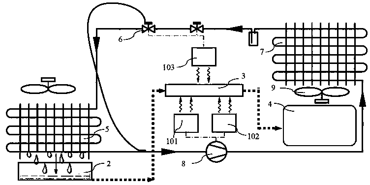
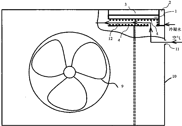
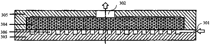
[0028] For the structural arrangement of the air conditioner outdoor unit applying the present invention, see figure 2 , the outdoor unit of the air conditioner includes an electric control box 1, a cooling fan 9, and a housing 10 with an air inlet 11. The electric control box 1 has built-in electric control components such as a power module 101, a drive module 102, and a control module 103. The lower side of 1 is provided with air flow channel 12, and air flows through air inlet 11, the inlet and outlet of air flow channel 12 successively under the drive of cooling fan 9, all can adopt prior art. The outdoor unit of the air conditioner also includes a condensed water compensation container 2, a cooling unit 3, a water evaporation unit 4 and a communication pipeline. The unit 3 is placed on the upper part of the electric control box 1, and the lower surface of the heating body 303 of the cooling unit 3 is closely attached to the upper surface of the electric control box 1, an...

Embodiment 2

[0032] The structural arrangement of the air conditioner outdoor unit applying the present invention is as follows: Figure 5 As shown, the outdoor unit of the air conditioner includes an electric control box 1, a cooling fan 9, a casing 10 and a vertical partition 13. 10 is provided with vertical dividing plate 13, is used for separating condenser 7, cooling fan 9 and compressor 8, valve body 6 and pipeline part, all can adopt prior art. The outdoor unit of the air conditioner also includes a condensed water compensation container 2, a cooling unit 3, a water evaporation unit 4 and a communication pipeline. The cooling unit 3 is arranged at the lower part of the electric control box 1, and the upper surface of the heating body 313 of the cooling unit 3 is closely attached to the The lower surface of the electric control box 1 is coated with heat-conducting resin or heat-conducting silica gel to conduct heat well, and the outer surface of the cooling unit 3 on the compressor 8...


PUM


Abstract

The invention provides an air-conditioning condensate water utilization device for cooling of an electronic control system of an outdoor unit. The device comprises an electric control box, a condensate water compensation container, a cooling unit and a water evaporation unit. Air conditioning condensate water flows from a water outlet pipe of a water collecting disc on the lower portion of an evaporator to a condensate water compensation container and then flows into the cooling unit after buffering and compensation, heat in the electric control box is taken away by a heating element of the cooling unit, and the condensate water flows to the water evaporation unit finally to be evaporated on the surface of an evaporation core. According to the device, the cooling capacity of an air conditioning is used, so that energy is saved; the condensate water is evaporated instead of being discharged, so that adverse effects are eliminated; self-driving of condensate water supply is achieved through the suction action of a capillary core of the cooling unit and the evaporation action of the water evaporation unit; the device has the advantages of being good in cooling effect, long in service life, low in maintenance cost, capable of achieving energy saving and emission reduction of the air conditioning and the like.

Description

technical field [0001] The invention relates to a device for utilizing condensed water of an air conditioner, in particular to a device for cooling an electric control system of an outdoor unit of an air conditioner by utilizing condensed water, and belongs to the field of energy saving and emission reduction of an air conditioner. Background technique [0002] The current air conditioner leads the condensed water to the outside through pipes and discharges it directly, which is easy to leave water marks on the wall, and even grow moss, which breeds mosquitoes and has an adverse impact on the environment. Moreover, the condensed water is directly discharged and not utilized, resulting in energy waste. [0003] The temperature of condensed water is low, and heat can be taken away when it evaporates or volatilizes. The existing condensed water reuse scheme (200410046327.9, the treatment device for the condensed water of the air conditioner; 200710137609.3, the cooling structur...

Claims


Application Information

Patent Timeline
Patent Type & Authority Applications(China)
IPC IPC(8): F24F1/42F24F1/24
Inventor 郑艺华刘君
Owner QINGDAO UNIV
Why Eureka
Try Eureka