Speed reducer testing equipment

A technology of testing equipment and reducer, applied in the field of construction machinery, can solve problems such as errors, reduce the measurement accuracy of an angle encoder, and achieve the effect of improving the angle measurement accuracy

Active Publication Date: 2014-04-02
BEIJING A&E TECH
View PDF7 Cites 32 Cited by
  • Summary
  • Abstract
  • Description
  • Claims
  • Application Information

AI Technical Summary

Problems solved by technology

[0003] In the existing reducer testing equipment, the output end of the reducer to be tested is connected coaxially with the loading mechanism, and the input end is connected coaxially with the input shaft of the servo motor through an angle encoder and other equipment. The shaft is coaxial with the connecting shaft, so the connecting shaft will inevitably be affected by the rotational torque transmitted by the servo motor, which will produce errors caused by the torque deformation of the connecting shaft itself, resulting in the torque angle measured by the angle encoder There is a large error with the actual torque angle of the reducer to be tested, which reduces the measurement accuracy of the angle encoder

Method used


Image

  • Speed reducer testing equipment
  • Speed reducer testing equipment
  • Speed reducer testing equipment

Examples


Embodiment Construction

[0019] The present invention will be described in detail below in conjunction with the accompanying drawings and embodiments.

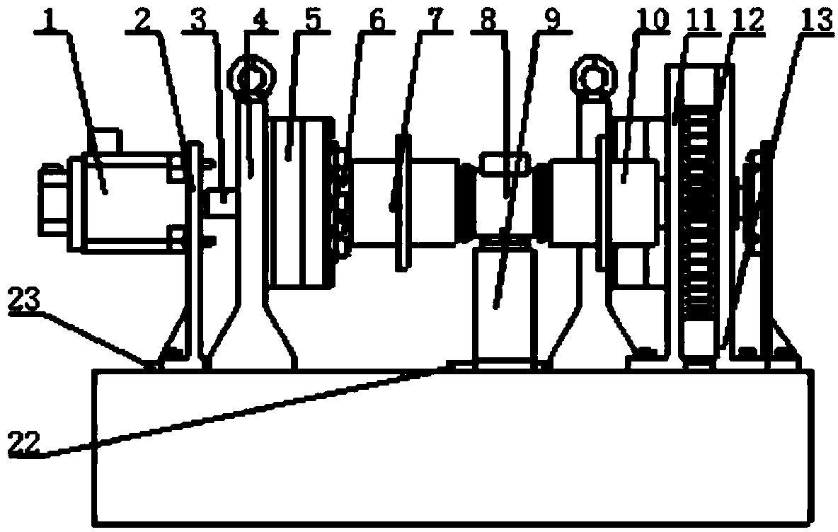
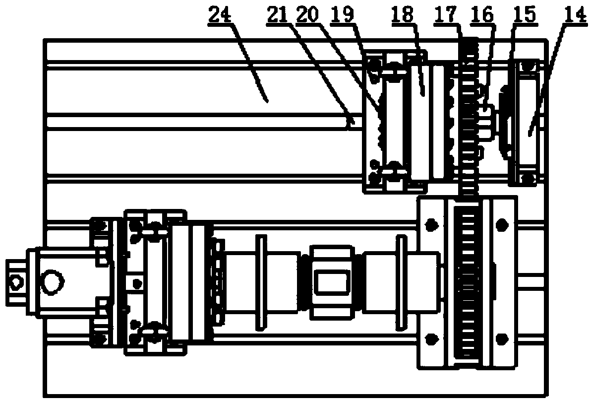
[0020] refer to figure 1 and figure 2 , figure 1 It is a schematic diagram of the front view structure of the reducer testing equipment according to the first embodiment of the present invention; figure 2 yes figure 1 The schematic diagram of the top view structure of the reducer test equipment in . The main components of the speed reducer test equipment include a support platform 24 and a servo motor 1 arranged on the support platform 24 , an increasing torque reducer 5 , a torque sensor 8 , an input runner 12 , an output runner 17 and an angle sensor 15 . In addition, the reducer test equipment also includes auxiliary components, such as servo motor bracket 2, first connecting shaft 3, increased torque reducer bracket 4, second connecting shaft 6, first coupling 7, torque sensor bracket 9, The second coupling 10 , the angle sensor bracket 14 ...


PUM


Abstract

The invention discloses a speed reducer testing equipment which is used for testing the return difference and the elastic constant of a speed reducer to be tested. The speed reducer testing equipment comprises a support platform, and a servo motor, an input rotating wheel, an output rotating wheel, load equipment and an angle sensor which are arranged on the support platform, wherein an output shaft of the servo motor is connected with one of a first side shaft and a second side shaft, which are opposite, of the input rotating wheel so as to drive the input rotating wheel to rotate around a first rotating shaft defined by the first side shaft or the second side shaft; the speed reducer to be tested and the angle sensor are respectively connected with a third side shaft and a fourth side shaft, which are opposite, of the output rotating wheel; the output rotating wheel is meshed with the input rotating wheel to further synchronously rotate around a second rotating shaft which is defined by the third side shaft or the fourth side shaft and parallel to the first rotating shaft; the angle sensor is used for obtaining a torque angle of the speed reducer to be tested. Due to the adoption of the mode, according to the speed reducer testing equipment disclosed by the invention, the angle measurement precision of the speed reducer to be tested is improved.

Description

technical field [0001] The invention relates to the technical field of engineering machinery, in particular to a speed reducer testing equipment. Background technique [0002] High-precision cycloidal pinwheel reducers are widely used in industrial robots, precision processing equipment, papermaking and printing machinery, medical equipment and other fields, and their performance directly affects the performance indicators of the final product. Taking industrial robots as an example, China is currently the country with the highest growth rate of demand for industrial robots in the world. In 2011, about 20,000 new industrial robots were added. If each set is equipped with 4 reducers, 80,000 reducers are needed, and This figure is expected to grow at a rate of 5% every year in the future, so it is very necessary and urgent to develop and manufacture a high-performance cycloid reducer that can meet the requirements. my country's current high-precision cycloidal reducer technol...

Claims


Application Information

Patent Timeline
Patent Type & Authority Applications(China)
IPC IPC(8): G01M13/02G01B21/22
CPCG01M13/027
Inventor 王春晓
Owner BEIJING A&E TECH
Why Eureka
Try Eureka