Coupling inductor and power converter

A technology of power converters and coupled inductors, which is applied in the field of circuits, can solve problems such as stray loss, magnetic flux leakage, and influence of metal parts, and achieve the effect of reducing magnetic flux leakage

Active Publication Date: 2014-04-02
HUAWEI TECH CO LTD
View PDF8 Cites 22 Cited by
  • Summary
  • Abstract
  • Description
  • Claims
  • Application Information

AI Technical Summary

Problems solved by technology

[0003] For example, taking a five-level power converter using a two-phase coupled inductor as an example, when the common mode current flows through the coils on the two magnetic columns of the coupled inductor, the directions of the magnetic fluxes generated by the coils on the two magnetic columns are opposite , therefore, the common-mode magnetic flux in the upper and lower yokes is zero, while the magnetic flux in the two magnetic columns will generate a large common-mode magnetic potential, resulting in magnetic flux leakage in the air, that is, the magnetic flux leakage caused by the common-mode current can not be ignored
[0004] Due to the large common mode current, there is a large leakage flux in the coupled inductor, the leakage flux will generate eddy current loss in the winding, and generate stray loss in the metal part outside the winding. At the same time, the leakage flux will also affect The normal operation of surrounding Hall sensors, current transformers (current transformer, CT) and other magnetic components

Method used


Image

  • Coupling inductor and power converter
  • Coupling inductor and power converter
  • Coupling inductor and power converter

Examples


Embodiment Construction

[0032] The following will clearly and completely describe the technical solutions in the embodiments of the present invention with reference to the accompanying drawings in the embodiments of the present invention. Obviously, the described embodiments are some of the embodiments of the present invention, but not all of them. Based on the embodiments of the present invention, all other embodiments obtained by persons of ordinary skill in the art without creative efforts fall within the protection scope of the present invention.

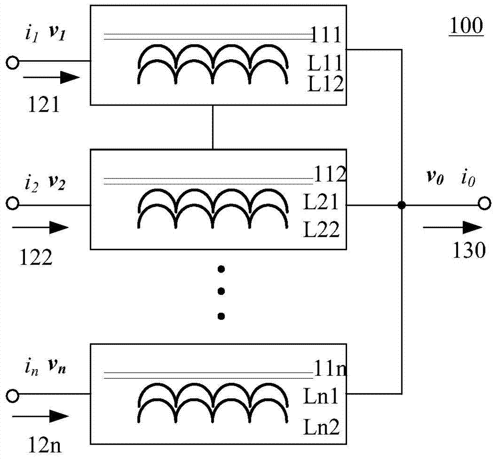
[0033] figure 1 is a schematic diagram of the structure of a coupled inductor 100 according to an embodiment of the present invention.

[0034]The coupled inductor 100 includes: at least two input terminals 121, 122, ..., 12n, an output terminal 130, a common magnetic core, at least two first windings L11, L21, ..., L31 and at least two second windings L12, L22, ..., L32. The common magnetic core includes at least two magnetic columns 111, 112, ..., ...


PUM


Abstract

The invention provides a coupling inductor and a power converter. The coupling inductor comprises at least two input ends, an output end, a common magnetic core, at least two first windings and at least two second windings, wherein the common magnetic core comprises at least two magnetic columns; the number of the magnetic columns corresponds to that of the input ends; each of the at least two magnetic columns is wound with a first winding and a second winding in parallel; the first windings and the second windings on the at least two magnetic columns are connected with each other between the at least two input ends and the output end to form mutually coupled inductors, so that when currents flowing into the at least two input ends are equal, the first winding and the second winding on each magnetic column generate opposite magnetic potentials. According to the technical scheme, when the currents flowing into the at least two input ends are equal, the first winding and the second winding on each magnetic column generate the opposite magnetic potentials, so that magnetic potentials generated by a common mode current offset each other, and leakage flux is reduced.

Description

technical field [0001] The invention relates to the field of circuits, in particular to a coupling inductor and a power converter. Background technique [0002] Currently, multilevel parallel converters are widely used. By using the interleaved parallel technology, the multilevel parallel converter can reduce the output ripple current and increase the output switching frequency, so the output inductance can be reduced, thereby reducing the volume and cost of the inductor. [0003] For example, taking a five-level power converter using a two-phase coupled inductor as an example, when the common mode current flows through the coils on the two magnetic legs of the coupled inductor, the directions of the magnetic fluxes generated by the coils on the two magnetic legs are opposite , therefore, the common-mode magnetic flux in the upper and lower yokes is zero, while the magnetic flux in the two magnetic columns will generate a large common-mode magnetic potential, resulting in m...

Claims


Application Information

Patent Timeline
Patent Type & Authority Applications(China)
IPC IPC(8): H01F38/14H01F27/24H01F27/30H02M1/00
CPCH01F27/38H01F38/023H01F2038/026H02M7/487
Inventor 叶飞刘云峰傅电波
Owner HUAWEI TECH CO LTD
Why Eureka
Try Eureka