Hollow manipulator

A manipulator, hollow technology, applied in the direction of manipulator, program control manipulator, chuck, etc., can solve the problems of no reserved space for installing expansion equipment, single structure, inconvenient manipulator optimization and expansion, etc.

Inactive Publication Date: 2014-04-30
AD TOYO LIGHTING GUANGZHOU
View PDF5 Cites 1 Cited by
  • Summary
  • Abstract
  • Description
  • Claims
  • Application Information

AI Technical Summary

Problems solved by technology

[0003] The manipulator in the prior art has a single structure and simple action, and there is no space reserved

Method used


Image

  • Hollow manipulator
  • Hollow manipulator

Examples


Embodiment 1

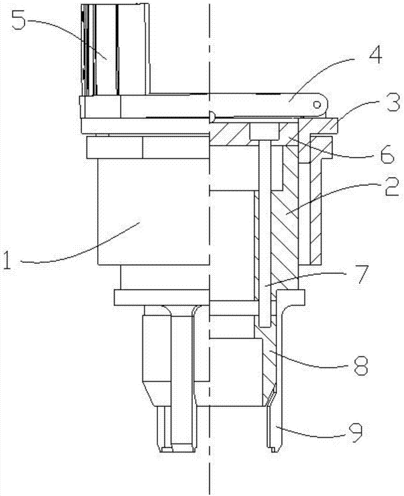
[0029] see figure 1 , is a schematic diagram of the half-section structure of the first embodiment of the hollow manipulator of the present invention. In the figure, the center line of the hollow manipulator is used as the dividing line, and the right side of the center line is sectioned to clearly observe the internal structure of the hollow manipulator. A hollow manipulator includes: an outer shell 1, an inner sleeve 2, a hinge frame 3, a top cover 4, a control cylinder 5, a top plate 6, connecting bolts 7, a hollow taper sleeve 8 and elastic gripper jaws 9.

[0030] The shell 1 protects the internal structure and connects with external devices.

[0031] The inner sleeve 2 is used to guide the connecting bolt 7 and is an important part inside the hollow manipulator; the inner sleeve 2 is installed inside the outer shell 1 .

[0032] The hinge frame 3 is used for installing the top cover 4 and the control cylinder 5; the hinge frame 3 is rigidly connected with the inner sle...

Embodiment 2

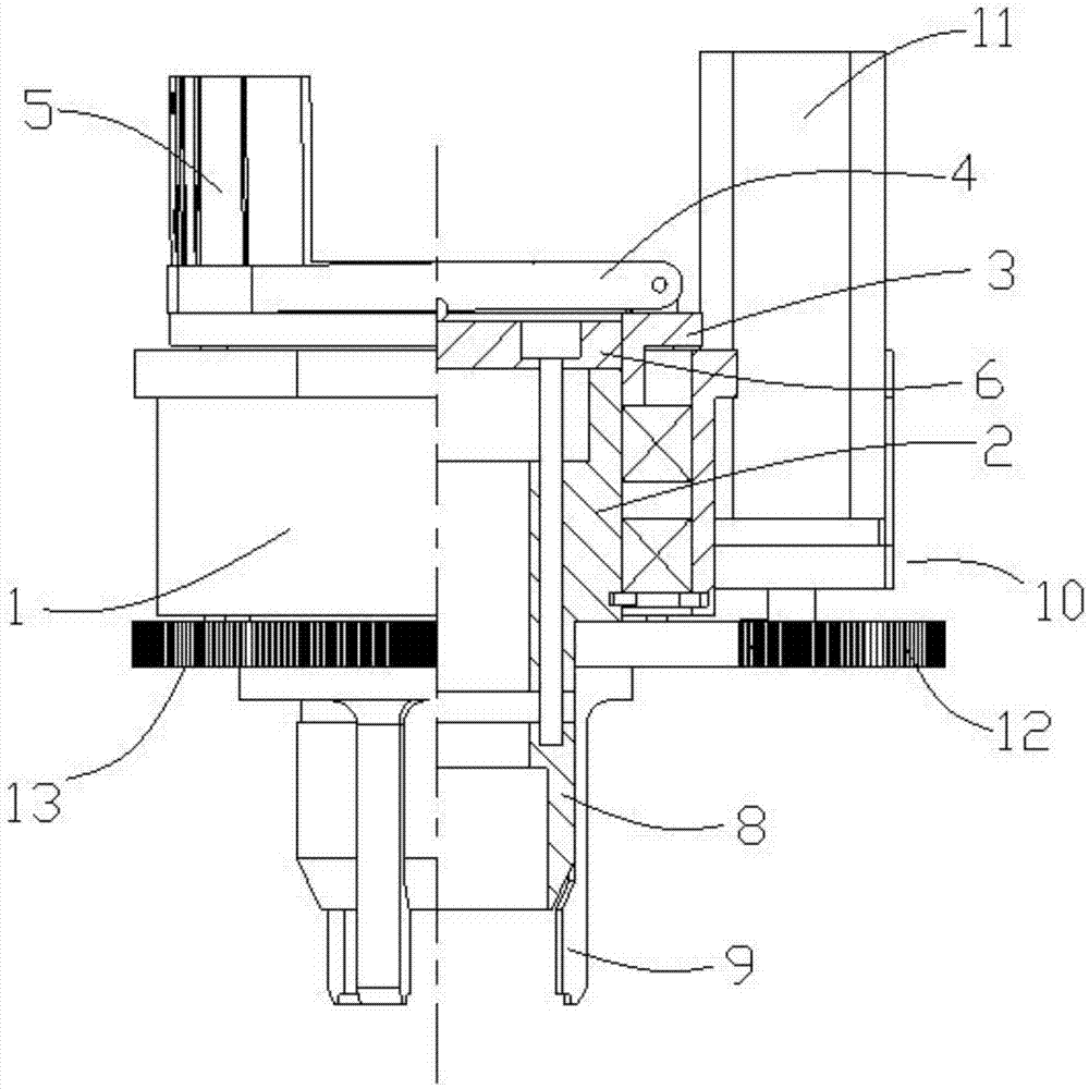
[0044] The difference from Embodiment 1 is that: on the original basis, a bearing and a rotating mechanism 10 are added, so that the hollow manipulator of the present invention has a rotating function.

[0045] see figure 2 , is a schematic diagram of the half-section structure of the second embodiment of the hollow manipulator of the present invention. In the figure, the center line of the hollow manipulator is used as the dividing line, and the right side of the center line is sectioned to clearly observe the internal structure of the hollow manipulator. In order to make the hollow manipulator of the present invention have the function of rotation, in this embodiment, the hollow manipulator of the present invention also includes a bearing (not shown) and a rotating mechanism 10; the bearing is installed between the inner sleeve 2 and the outer shell 1; the rotating mechanism 10 is installed on the outside of enclosure 1.

[0046] Rotating mechanism 10 comprises: rotating ...


PUM


Abstract

The invention provides a hollow manipulator. The hollow manipulator comprises a housing, an inner sleeve, a hinge frame, a top cover, a control cylinder, a top plate, a connecting bolt, a hollow taper sleeve and an elastic clamping jaw; the inner sleeve is arranged inside the housing; the hinge frame is in rigid connection with the inner sleeve; the top cover is hinged to the hinge frame; the control cylinder is arranged on the hinge frame; the top cover is connected with the control cylinder; the top plate is located under the top cover; the top plate is in rigid connection with the upper end of the connecting bolt; the connecting bolt penetrates the inner sleeve; the lower end of the connecting bolt is in rigid connection with the hollow taper sleeve; the elastic clamping jaw is provided with the inner taper surface; the elastic clamping jaw is in rigid connection with the inner sleeve. According to the hollow manipulator, the middle is provided with a hollow structure which can be utilized as an observation hole and can even be provided with an extension device and accordingly the additional extension function can be achieved.

Description

technical field [0001] The invention relates to the field of industrial production automation, in particular to a hollow manipulator. Background technique [0002] In industrial automatic production, it is often necessary to move or assemble workpieces. The movement or assembly of workpieces is usually done by industrial manipulators. However, the industrial manipulator currently used only has a clamping mechanism, which can only simply complete the clamping action on the workpiece, or cooperate with the movement mechanism to transport the workpiece. With the increasing degree of industrial automation, manipulators with only clamping functions can no longer fully meet the needs of modern automated production. For example, in order to realize the intelligence of the manipulator, it is necessary to install a visual recognition system on the manipulator to intelligently identify the clamped workpiece; another example, to realize the detection of the workpiece, install a detec...

Claims


Application Information

Patent Timeline
IPC IPC(8): B25J15/08B25J9/08B25J19/04
Inventor 关崇安
Owner AD TOYO LIGHTING GUANGZHOU
Why Eureka
Try Eureka