
Stone cutting machine with fixing and limiting device
A limit device, cutting machine technology, applied in the direction of stone processing equipment, work accessories, manufacturing tools, etc., can solve the problems of inaccurate cutting, low work efficiency, waste, etc., to improve product qualification rate, improve work efficiency, structure simple effect
- Summary
- Abstract
- Description
- Claims
- Application Information
AI Technical Summary
Problems solved by technology
Method used
Image

Examples
Embodiment Construction
[0013] The present invention will be described in detail below in conjunction with the accompanying drawings and specific embodiments, wherein the schematic embodiments and descriptions are only used to explain the present invention, but are not intended to limit the present invention.
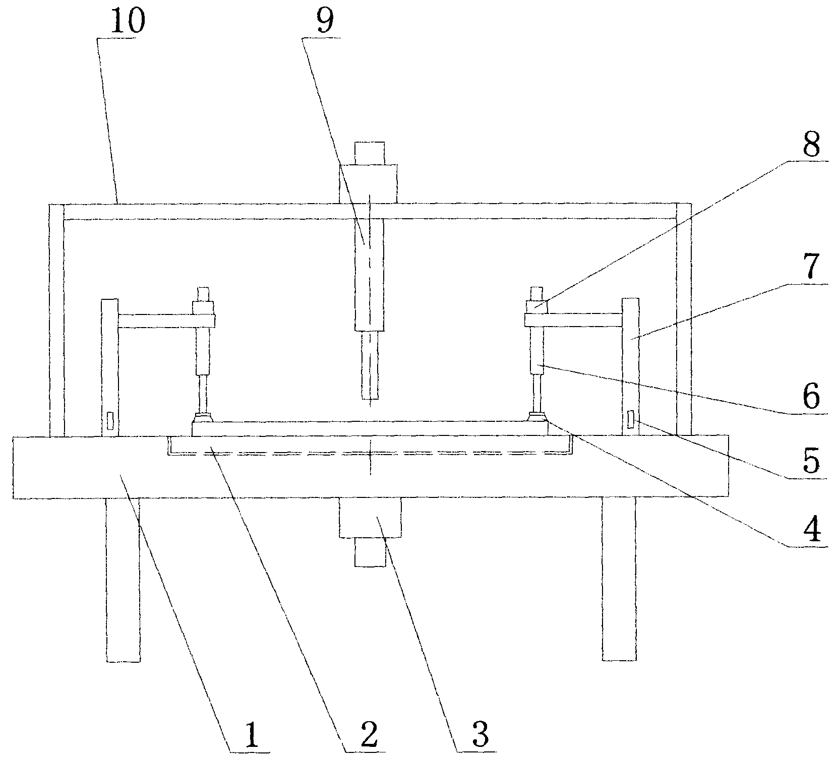
[0014] Such as figure 1 As shown, a stone cutting machine with a fixed limit device described in this specific embodiment includes a workbench 1, a lower frame 10 is arranged on the workbench 1, and a saw head device 9 is arranged on the lower frame 10; An inverted L-shaped support 7 is respectively arranged in the middle part of the left and right sides of the lower frame 10 on the upper surface of the workbench 1. The outer end of the horizontal bar of the inverted L-shaped support 7 is provided with a telescopic cylinder 6. The upper end of the telescopic cylinder 6 is connected to A servo motor 8, a suction cup 4 is connected to the telescopic cylinder head at the lower end of the telescop...
PUM
 Abstract
Description
Claims
Application Information