Tandem type multi-terminal direct-current power transmission system and loss compensation method thereof

A multi-terminal DC and power transmission system technology, applied in the direction of parallel operation of DC power supplies, power transmission AC networks, etc., can solve problems such as active/reactive power fluctuations, increased design margins of converter station equipment, and increased system instability , to achieve the effect of reducing active and reactive power demand changes, compensating for power loss, and reducing the increase in DC voltage

Active Publication Date: 2014-04-30
HITACHI ENERGY SWITZERLAND AG
View PDF1 Cites 4 Cited by
  • Summary
  • Abstract
  • Description
  • Claims
  • Application Information

AI Technical Summary

Problems solved by technology

However, when the DC resistance increases, the DC voltage at the current setting terminal will also increase, which increases the change in the active and reactive power requirements of the converter station, and also needs to increase the design margin of the equipment in the station
For example, in an 800kV / 3200MW unipolar series four-terminal DC transmission system (two rectifier stations, two inverter stations), for every 1Ω increase in the total DC transmission line, the DC voltage of the converter station at the current setting end will increase by 4kV , the firing angle changes by about 1.73 degrees, which will cause large fluctuations in active / reactive power
Usually, the resistance value of the DC transmission line changes by several ohms, which will increase the design margin of the converter station equipment, and the fluctuation of the active / reactive power of the converter station during the control will also increase the instability of the system

Method used


Image

  • Tandem type multi-terminal direct-current power transmission system and loss compensation method thereof
  • Tandem type multi-terminal direct-current power transmission system and loss compensation method thereof
  • Tandem type multi-terminal direct-current power transmission system and loss compensation method thereof

Examples


Embodiment Construction

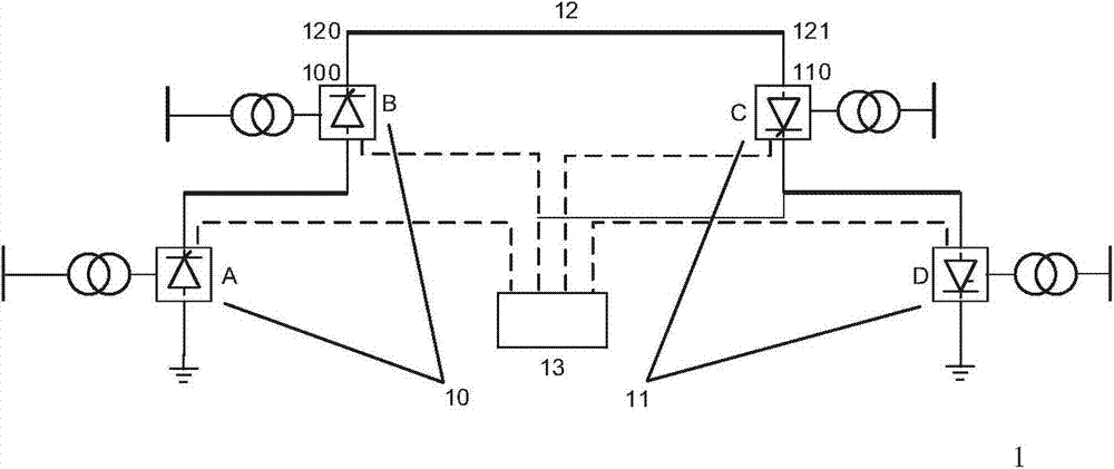
[0012] figure 1 A series multi-terminal DC power transmission system according to an embodiment of the present invention is shown. Such as figure 1 As shown, the series multi-terminal direct current transmission system 1 is a unipolar type, which includes a first converter station unit group 10, a second converter station unit group 11, and a high-voltage DC pole line including a first end 120 and a second end 121 12 and controller 13. The first converter station unit group 10 includes the first converter station unit A and the first converter station unit B in series in sequence, and the second converter station unit group 11 includes the second converter station unit C and the first converter station unit C in series in sequence. Two converter station unit D. Those skilled in the art should understand that for a series multi-terminal direct current transmission system, the number of first converter station units included in the first converter station unit group 10 may be...


PUM


Abstract

The invention provides a tandem type multi-terminal direct-current power transmission system and a loss compensation method thereof. The system comprises a first converter station unit group, a second converter station unit group, and a controller. The controller is capable of controlling one converter station unit among the at least one first converter station unit and a plurality of second converter station units to work as a current control terminal so as to maintain the constant state of the direct current, obtaining information including direct-current voltage values of the at least one first converter station unit and the plurality of second converter station units and the current value of a high-voltage direct-current polar line, and adjusting the direct voltage of at least one non-constant current terminal converter station unit among the at least one first converter station unit and the plurality of second converter station units based on the information so as to compensate the power loss of the high-voltage direct-current polar line conveniently. With the system and the method, the power loss of the high-voltage direct-current polar line can be compensated and the direct voltage of the current setting terminal can be decreased.

Description

technical field [0001] The invention relates to a series multi-terminal direct current transmission system and a loss compensation method. Background technique [0002] There are two common types of multi-terminal DC transmission systems: parallel multi-terminal direct current transmission system and series multi-terminal direct current transmission system. The DC side of each converter station of the parallel multi-terminal direct current transmission system is connected together in parallel through a transmission line; while the DC side of each converter station of the series multi-terminal direct current transmission system is connected together in series through a direct current transmission line. In the case of short distance between converter stations and difficult voltage insulation design, the multi-terminal direct current transmission system has certain technical advantages compared with the parallel multi-terminal direct current transmission system. [0003] The D...

Claims


Application Information

Patent Timeline
IPC IPC(8): H02J1/12H02J3/36
CPCY02E60/60
Inventor 苑春明杨晓波姚大伟
Owner HITACHI ENERGY SWITZERLAND AG
Why Eureka
Try Eureka