Electromagnetic shielding light window based on four-external-tangent orthogonal ring units and sub ring units

An electromagnetic shielding and basic unit technology, applied in the direction of magnetic/electric field shielding, electrical components, etc., can solve the problems of low imaging quality impact, stray light distribution concentration, etc., to achieve the effect of improving electromagnetic shielding effect and improving uniformity

Active Publication Date: 2014-04-30
HARBIN INST OF TECH
View PDF9 Cites 4 Cited by
  • Summary
  • Abstract
  • Description
  • Claims
  • Application Information

AI Technical Summary

Problems solved by technology

[0019] The purpose of the present invention is to overcome the deficiencies of the above-mentioned existing optical window electromagnetic shielding technical solutions, especially for the existing single-layer grid metal grid, single-layer ring grid, double-layer grid and ring grid. To solve the problem of relatively concentrated stray light distribution caused by sub-diffraction, an electromagnetic shielding light window based on four circumscribed orthogonal rings and sub-ring units has been developed to achieve depth averaging of high-order diffraction and extremely low impact on imaging quality the goal of

Method used


Image

  • Electromagnetic shielding light window based on four-external-tangent orthogonal ring units and sub ring units
  • Electromagnetic shielding light window based on four-external-tangent orthogonal ring units and sub ring units
  • Electromagnetic shielding light window based on four-external-tangent orthogonal ring units and sub ring units

Examples


Embodiment Construction

[0052] The present invention is further described below with reference to accompanying drawing and preferred embodiment:

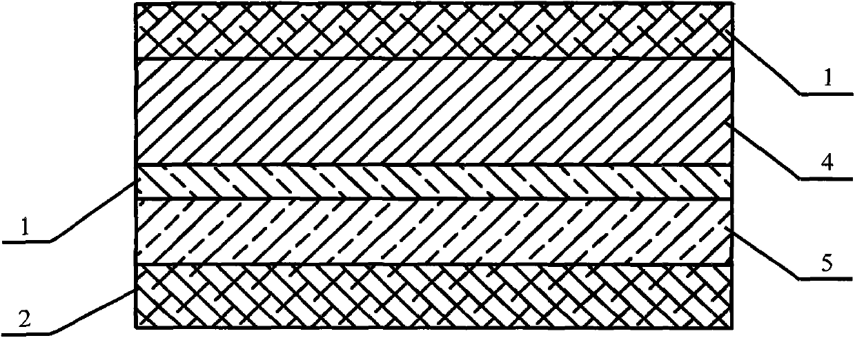
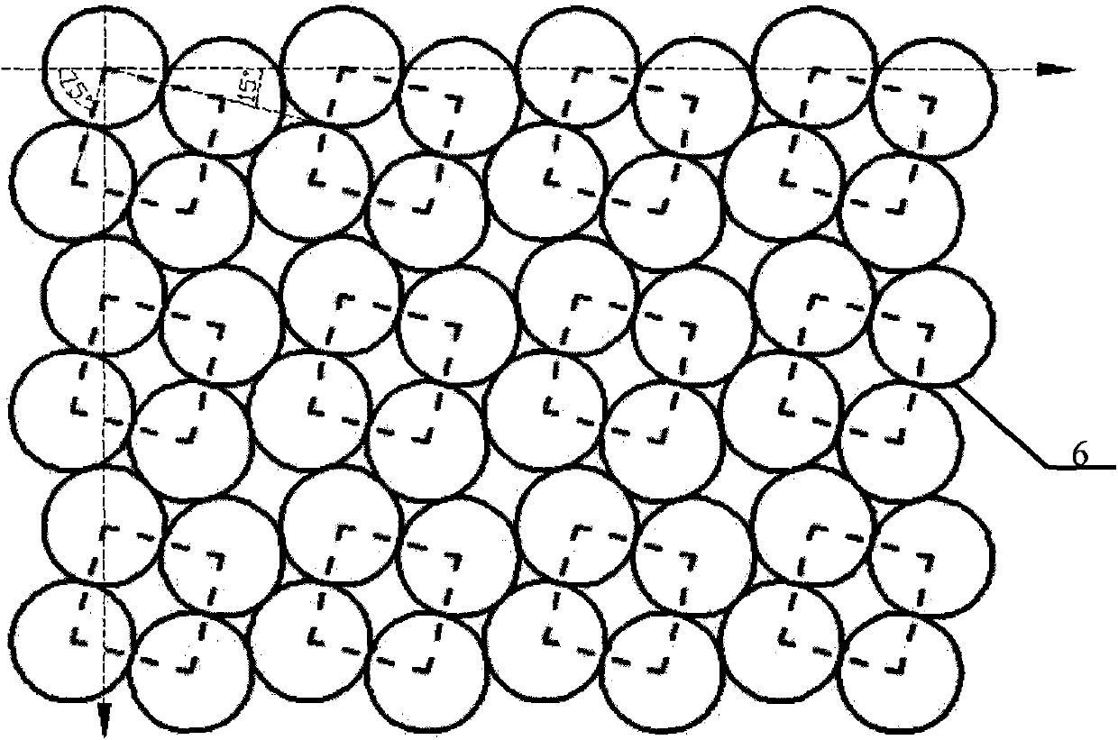
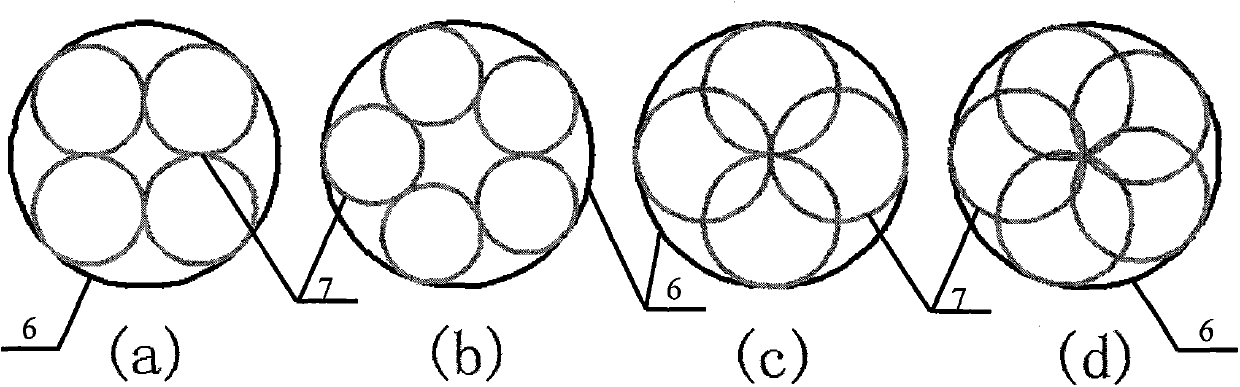
[0053]Based on the electromagnetic shielding light window of four circumscribed orthogonal rings and sub-ring units, the metal grid 5 in the electromagnetic shielding light window consists of metal rings of the same diameter as the basic ring 6 to form a four circumscribed orthogonal ring unit And according to the two-dimensional orthogonal arrangement closely arranged; wherein, the four circumscribed orthogonal ring units are composed of four basic rings 6 arranged in two-dimensional orthogonal and circumscribed connected, the four circumscribed orthogonal ring units The angle between the direction of the connecting line of the center of the basic ring 6 and the two-dimensional orthogonal arrangement of the four circumscribed orthogonal ring units is 15° or 75°, and the adjacent four circumscribed orthogonal ring units pass through the Adjacent basic ring...


PUM


Abstract

The invention relates to an electromagnetic shielding light window based on four-external-tangent orthogonal ring units and sub ring units and belongs to the technical field of electromagnetic shielding. Metal rings with the same diameter are used as basic rings to form the four-external-tangent orthogonal ring units and are densely connected and arranged in a two-dimensional orthogonal mode to form metal grids. Each four-external-tangent orthogonal ring unit is formed by communicating the four basic rings in an external tangent mode, wherein the four basic rings are arranged in a two-dimensional orthogonal mode. The included angle between the line connection direction of the centers of the basic rings and the array direction of the four-external-tangent orthogonal ring units which are arranged in the two-dimensional orthogonal mode is 15 degrees or 75 degrees, the adjacent basic rings of the adjacent four-external-tangent orthogonal ring units are communicated in an external tangent mode, and sub rings communicated with the basic rings in an internal tangent mode are arranged in the basic rings. Metal which ensures reliable electric connection between points of tangency of the metal rings is overlapped through lines or arranged at the joints where the rings are communicated in the external tangent mode, and it is ensured that all the rings are mutually conducted. According to the structure of the metal grids, nonuniformity of high-level diffraction light intensity distribution of the grids can be obviously relieved, stray light caused by diffraction can be distributed more uniformly, and influences on imaging are less.

Description

technical field [0001] The invention belongs to the field of electromagnetic shielding of optical transparent parts, in particular to an electromagnetic shielding light window based on four circumscribed orthogonal rings and sub-ring units. Background technique [0002] With the widening and increasing intensity of the electromagnetic wave application spectrum, the requirements for electromagnetic shielding light windows used in aerospace equipment, advanced optical instruments, communication equipment, medical diagnostic instruments and security facilities are getting higher and higher, mainly requiring light windows While having a super strong broadband electromagnetic shielding ability, it also has a very high light transmittance, and the less impact on optical imaging, observation, and detection, the better. For example, the optical window of an aircraft in the field of aerospace equipment must achieve high-quality isolation of electromagnetic signals inside and outside ...

Claims


Application Information

Patent Timeline
Patent Type & Authority Applications(China)
IPC IPC(8): H05K9/00
Inventor 陆振刚谭久彬林沈王赫岩
Owner HARBIN INST OF TECH
Why Eureka
Try Eureka