roof structure for vehicles

A roof, vehicle technology, applied in the superstructure, vehicle components, sub-assembly of the upper structure, etc., to achieve the effect of improving the aesthetics and improving the bonding strength

Inactive Publication Date: 2016-04-06
HONDA MOTOR CO LTD
View PDF5 Cites 1 Cited by
  • Summary
  • Abstract
  • Description
  • Claims
  • Application Information

AI Technical Summary

Problems solved by technology

[0004] However, although most of the groove portion is blocked by the top plate, the remaining portion that is not blocked is clearly seen as an unnecessary gap.

Method used


Image

  • roof structure for vehicles
  • roof structure for vehicles
  • roof structure for vehicles

Examples


Embodiment

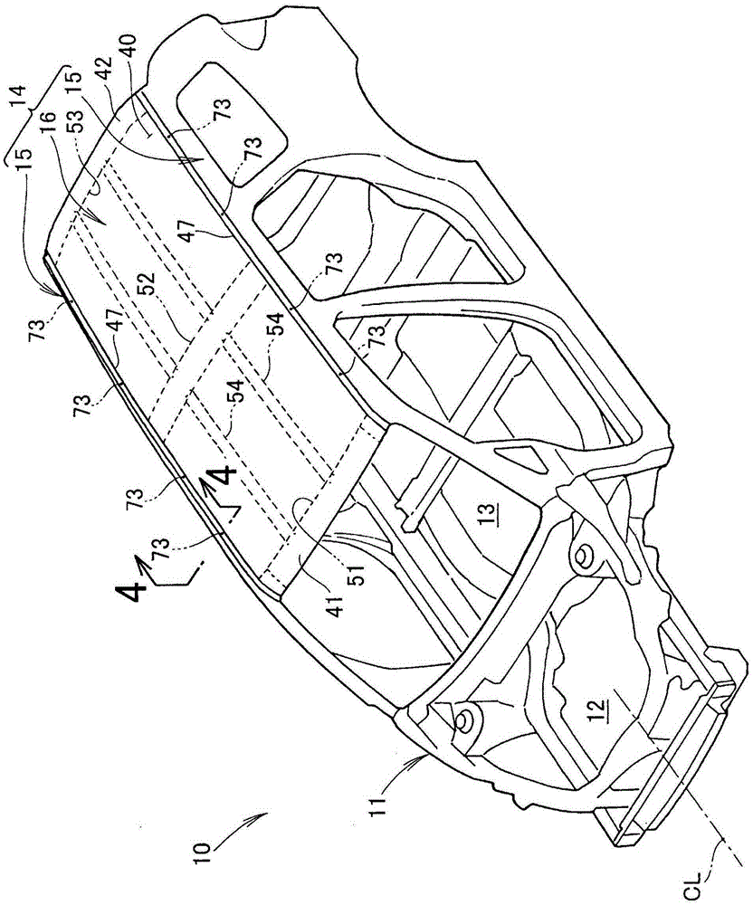
[0040] Such as figure 1 As shown, the vehicle 10 is, for example, a passenger car, and a front engine room 12 and a vehicle room 13 located directly behind the engine room 12 are formed inside a vehicle body 11 . The vehicle body 11 is formed of a monocoque, and is formed in a left-right symmetrical shape with respect to a vehicle width centerline CL extending in the vehicle front-rear direction passing through the center of the vehicle 10 in the vehicle width direction.

[0041] The roof structure 14 (hereinafter also referred to as "roof 14") of the vehicle body 11 is a portion covering the upper part of the vehicle compartment 13, and consists of left and right roof rails 15, 15 extending in the front-rear direction of the vehicle body, and The roof assembly 16 supported by the left and right roof rails 15 and 15 is constituted.

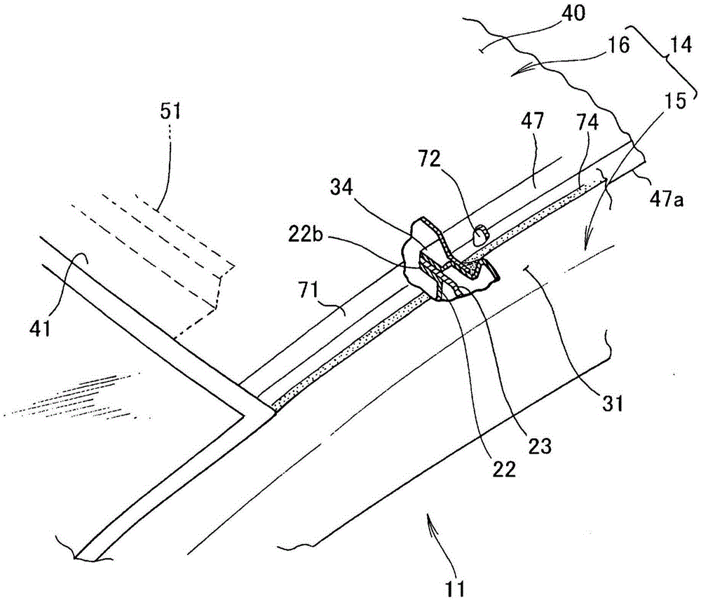
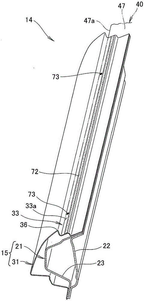
[0042] Such as figure 1 , figure 2 and image 3 As shown, the left and right roof side rails 15, 15 are composed of the following parts: lef...


PUM


Abstract

The left and right roof rails (15, 15) for supporting the roof panel (40) are composed of left and right inner rails (21, 21) and left and right outer panels (31, 31) located on the outside of the left and right inner rails in the vehicle width direction. constitute. The left and right outer panels form an intermediate step (33, 33) and a lower upper outer flange (34, 34) in a stepped shape from the upper end (36, 36) toward the inside in the vehicle width direction. The upper outer flange is joined to the upper surfaces (21a, 21a) of the left and right inner beams. The left and right end portions (47, 47) of the top plate are joined to the stepped surface (33a, 33a) of the stepped portion by the bonding portion (72, 72) and the temporary fixing portion (73, 73). The temporary fixing part is a welded part that is temporarily fixed until the bonding part can exert adhesive force, and is covered with a filler layer (74, 74) filled to the stepped part.

Description

technical field [0001] The present invention relates to a roof structure for a vehicle in which a roof is supported by left and right roof side rails extending in the front-rear direction of a vehicle body. Background technique [0002] The roof provided on the upper portion of the vehicle body is configured to support left and right end portions of a roof panel via left and right roof side sills. The left and right roof side rails and the left and right ends of the roof plate are superimposed on each other in the vertical direction and are joined by spot welding. In order to realize the spot welding in the up-down direction, the joint portions between the left and right roof side rails and the left and right end portions of the top plate are configured as grooves that open upward. This groove portion is plugged with a decorative molding. Since the traces of spot welding appearing at the bottom of the groove are covered with the decorative molding, the appearance of the ve...

Claims


Application Information

Patent Timeline
Patent Type & Authority Patents(China)
IPC IPC(8): B62D25/06
CPCB62D25/02B62D25/06B62D25/07B62D27/026B62D27/02
Inventor 飞田一纪沟畠仁
Owner HONDA MOTOR CO LTD
Why Eureka
Try Eureka